Filter element with guide shaft

A filter element and guide channel technology, which is applied in the direction of dispersed particle filtration, vehicle parts, household appliances, etc., and can solve the problem of damage to corrugated boxes

Active Publication Date: 2012-12-26
CARL FREUDENBERG KG
View PDF5 Cites 1 Cited by
  • Summary
  • Abstract
  • Description
  • Claims
  • Application Information

AI Technical Summary

Problems solved by technology

Said cutter may damage the corrugated box

Method used


Image

  • Filter element with guide shaft
  • Filter element with guide shaft
  • Filter element with guide shaft

Examples


Embodiment Construction

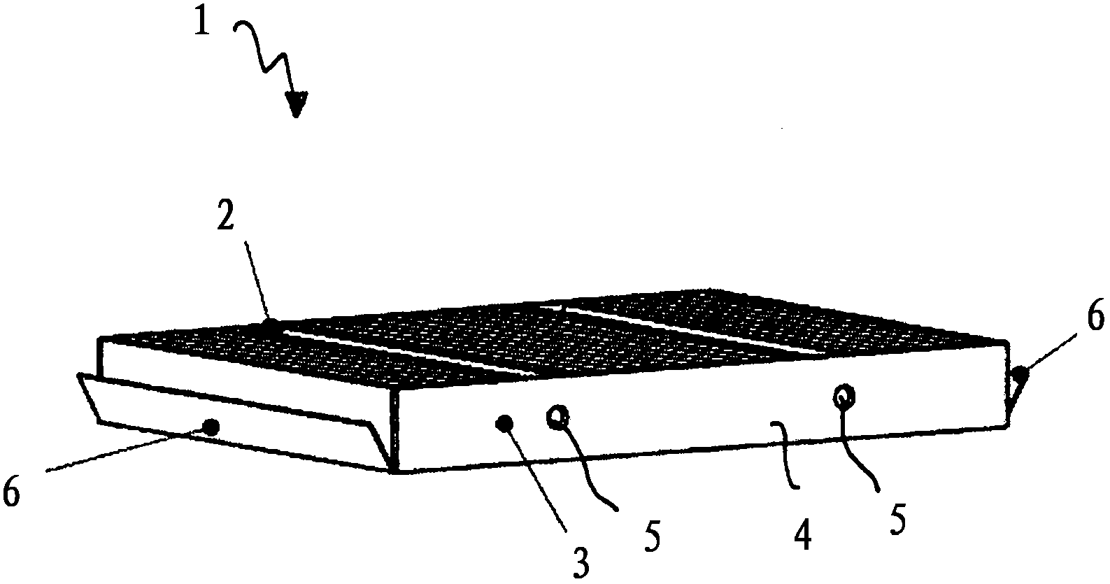
[0040] figure 1 A cuboid filter element 1 is shown in perspective for installation in a housing of a ventilation or air conditioning system. The filter element 1 comprises a bellows box 2 which has bellows and an end face which can face the wall of the housing. The end side 3 is surrounded by an edge strip 4 into which a through-hole 5 for a guide pin is introduced.

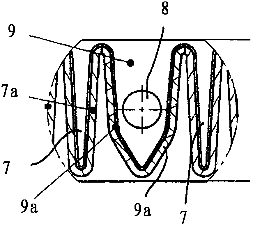
[0041] Furthermore, the filter element 1 has side strips 6 from which V-shaped sealing webs protrude. The corrugated box 2 is made of non-woven fabric. The edge strip 5 is likewise made of non-woven fabric. The side strips 6 are also made of non-woven fabric, apart from the V-shaped protruding sealing flaps.

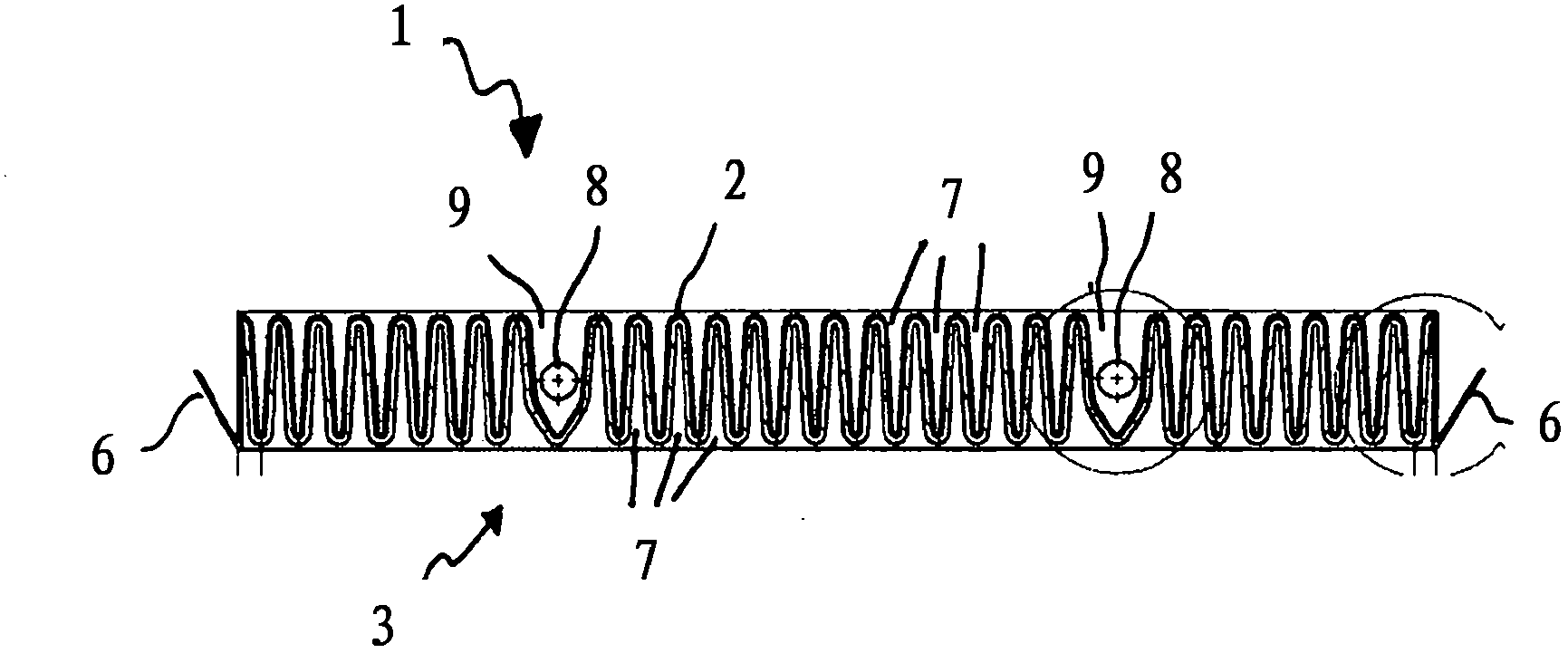
[0042] figure 2 Shows figure 1 A cross-sectional view of a cube-shaped filter element 1 .

[0043] figure 2 Shown is a filter element 1 for installation in a housing of a ventilation or air-conditioning system, which comprises a bellows box 2 with corrugations and an end side 3 which can face the ...


PUM


Abstract

A Filter element (1) for insertion into a housing of a ventilation unit or air conditioner, comprising a bellows (2) with folds and a front side (3) which can face a wall of the housing, wherein the folds on the front side define fold cross-sectional surfaces (7,9); the front side is provided with at least one guiding slot (8); and a fold cross-sectional surface (9) in the area of a guiding slot( 8) has a geometry that is different from the fold cross-sectional surface of a multiplicity of folds (7).In view of the task of providing an efficient filter element which, after problem-free manufacture is equipped with guiding slots (8) into which guide pins can be inserted, and characterized in that a multiplicity of regular fold walls (7a) is provided, wherein each two flanking walls (9a) flank the guiding slot (8).

Description

technical field [0001] The invention relates to a filter element according to the preamble of claim 1 . Background technique [0002] A filter element is known from DE 10 2005 048 841 B3, which is installed in the housing of a ventilation system of a motor vehicle. Specifically, in such a filter device, the guide pins of the housing correspond to the guide channels in the filter element. [0003] In this way, a mechanical coding is to be achieved which ensures that only filter elements suitable for the housing are inserted into the housing. [0004] The guide channels are here oriented parallel to the corrugation ridges of the corrugations of the folding corrugated box or parallel to the direction of the folds. Furthermore, the guide channel is aligned parallel to the corrugated wall. [0005] The corrugated box is surrounded by edge strips, in which through-holes are machined. Guide pins pass through these through holes and then run parallel to the corrugated walls or r...

Claims


Application Information

Patent Timeline
Patent Type & Authority Applications(China)
IPC IPC(8): B01D46/00B01D46/42F24F13/28F24F8/108
CPCB60H2003/065F24F3/1603B60H3/0658B01D46/521F24F8/10F24F8/108
Inventor U·黑夫纳M·克格尔R·多布纳A·布罗伊尔
Owner CARL FREUDENBERG KG
Why Eureka
Try Eureka