Dispenser

A dispensing machine and dispensing device technology, applied in the field of dispensing machines, can solve the problem of inconvenient contact surface at the end, and achieve the effect of simple structure, flexible control and small volume

Inactive Publication Date: 2012-12-26
SHANDONG ATAW IND ROBOT TECH
View PDF7 Cites 8 Cited by
  • Summary
  • Abstract
  • Description
  • Claims
  • Application Information

AI Technical Summary

Problems solved by technology

[0002] In industrial production, in order to facilitate the installation of some parts, it is usually necessary to dispensing the ends of the parts. For some tiny parts, it is very inconvenient to dispensing glue due to their small size and small contact surface at the ends. At present, There is no good equipment to solve this problem

Method used


Image

  • Dispenser
  • Dispenser
  • Dispenser

Examples


Embodiment Construction

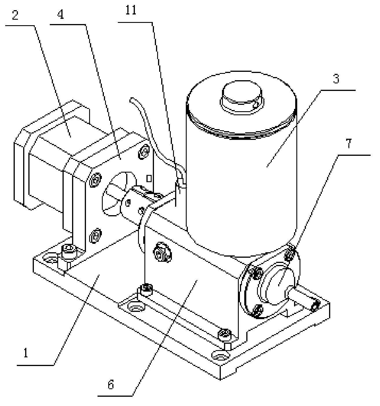
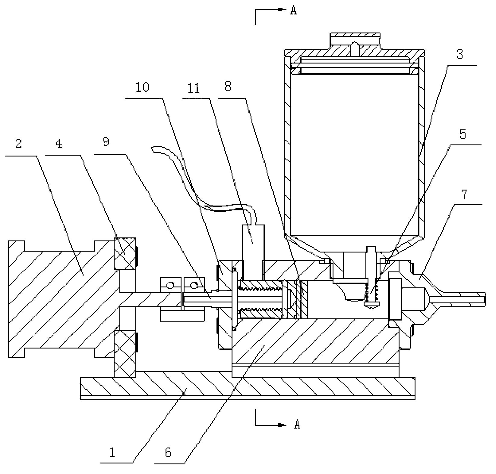
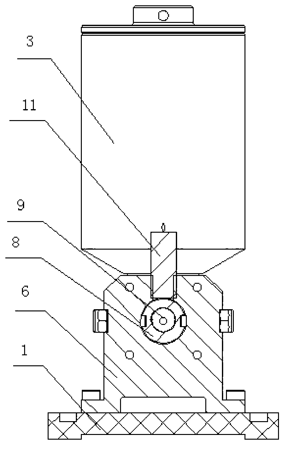
[0010] Such as figure 1 , figure 2 , image 3 As shown, a glue dispensing machine includes a base 1, a motor 2, a glue tank 3 and a glue dispensing device, the motor 2 is fixed on one end of the base 1 through a mounting plate 4, the glue dispensing device is fixed on the other end of the base, and the glue dispensing device A glue tank 3 is fixed on the top, and a check valve 5 is provided at the mouth of the glue tank; the dispensing device includes a cavity 6, the front end of the cavity 6 is fixed with a glue nozzle 7, and a piston 8 is arranged in the cavity 6, and the piston 8 There are symmetrical grooves on both sides, the piston 8 is fixed on the screw 9, the screw 9 is fixed at the end of the cavity 6 through the end cover 10, the end of the screw 9 is connected with the output shaft of the motor 2 through a coupling, and the outside of the cavity 6 is also Wrapped with a layer of heating film.

[0011] A sensor 11 is also provided at the end of the cavity 6 abov...


PUM


Abstract

The invention discloses a dispenser, relating to a gluing device. The dispenser comprises a pedestal, a motor, a glue tank and a dispensing device, wherein the motor is fixedly arranged at one end of the pedestal through a mounting plate; the dispensing device is fixedly arranged at the other end of the pedestal; the glue tank is fixedly arranged above the dispensing device; a one-way valve is arranged at an opening of the glue tank; the dispensing device comprises a cavity; the front end of the cavity is fixed with a glue discharge nozzle; a piston is arranged in the cavity; symmetric grooves are arranged on two sides of the piston; the piston is fixedly arranged on a screw; the screw is fixedly arranged at the tail end of the cavity through an end cover; the tail end of the screw is connected with a motor output shaft through a coupling; and a heating film is also wound outside the cavity. The dispenser has the advantages of simple structure, small size, convenience in control and capabilities of realizing flexible control to finish quantitative feed and discharge functions of glue.

Description

technical field [0001] The invention relates to a gluing device, in particular to a gluing machine. Background technique [0002] In industrial production, in order to facilitate the installation of some parts, it is usually necessary to dispensing the ends of the parts. For some tiny parts, it is very inconvenient to dispensing glue due to their small size and small contact surface at the ends. At present, There is no good equipment to solve this problem. Contents of the invention [0003] The object of the present invention is to provide a glue dispenser to solve the above problems. [0004] The technical solution adopted by the present invention to solve its technical problems is: a glue dispensing machine, which is characterized in that it includes a base, a motor, a glue tank and a glue dispensing device, the motor is fixed on one end of the base through a mounting plate, and the glue dispensing device is fixed on On the other end of the base, a glue tank is fixed a...

Claims


Application Information

Patent Timeline
Patent Type & Authority Applications(China)
IPC IPC(8): B05C5/02B05C11/10
Inventor 张乐贡李元波张溥
Owner SHANDONG ATAW IND ROBOT TECH
Why Eureka
Try Eureka