Deformable baffle of conveying belt

A conveyor belt and baffle technology applied in the field of conveyor belts to achieve the effects of low manufacturing cost, convenient application, and simple structure

Inactive Publication Date: 2012-12-26
昆山特力伯传动科技有限公司
View PDF9 Cites 3 Cited by
  • Summary
  • Abstract
  • Description
  • Claims
  • Application Information

AI Technical Summary

Problems solved by technology

Therefore, it is possible to provide different baffles when installing

Method used


Image

  • Deformable baffle of conveying belt

Examples


Embodiment Construction

[0020] Several embodiments of the present invention are discussed in detail below with reference to the accompanying drawings.

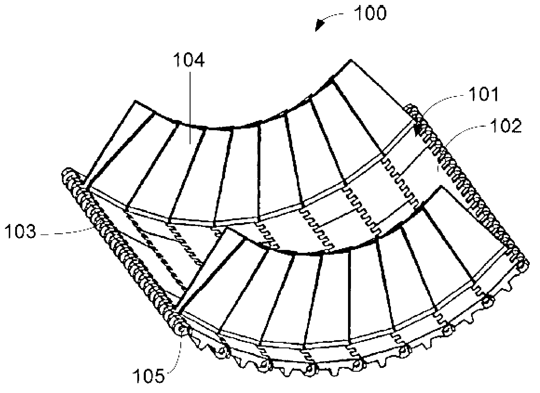
[0021] figure 1 The basic structure of the deformable baffle for the conveyor belt of the present invention is schematically shown. As shown in the figure, the deformable baffle 100 of the conveyor belt of the present invention mainly includes: a baffle 101 , a baffle 102 , a collar part 103 , a flap 104 and a connecting rod 105 .

[0022] exist figure 1 In the shown embodiment, there are a plurality of baffle plates 101 arranged side by side, and these baffle plates 101 further include: a baffle plate 102, and sleeves arranged in rows on the two long sides of the baffle plate 102 at predetermined intervals. The ring component 103 and the two flaps 104 are respectively pivotally connected to the two short sides of the blocking piece 102 .

[0023] In addition, the connecting rod 105 passes through a row of collar parts 103 on respective sides of t...


PUM


Abstract

The invention provides a deformable baffle of a conveying belt. The deformable baffle comprises a plurality of baffles, a stop sheet, ferrule components, two turning plates and a connecting rod, wherein the ferrule components are arranged on two long side edges of the stop sheet in rows at a predetermined space respectively; the two turning plates are pivotally connected to two short side edges of the stop sheet respectively; and the connecting rod penetrates through a row of ferrule components on one sides of two adjacent baffles in the baffles respectively. The deformable baffle has a simple structure, is low in manufacturing cost and can be conveniently applied to various conveying belts.

Description

technical field [0001] The invention relates to the field of conveyor belts, in particular to a deformable baffle for a conveyor belt. Background technique [0002] In the middle of the 17th century, the United States began to use aerial cableways to convey bulk materials; in the middle of the 19th century, conveyor belt conveyors of various modern structures appeared one after another. In 1868, belt conveyors appeared in the UK; in 1887, screw conveyors appeared in the United States; in 1905, steel belt conveyors appeared in Switzerland; in 1906, inertial conveyors appeared in the UK and Germany. Since then, the conveyor belt conveyor has been continuously improved under the influence of technological progress in machinery manufacturing, electrical machinery, chemical industry and metallurgical industry. Become an indispensable part of the mechanization and automation of material handling systems. [0003] In order to ensure that the materials on the conveyor belt will no...

Claims


Application Information

Patent Timeline
Patent Type & Authority Applications(China)
IPC IPC(8): B65G15/30
Inventor 朱井钟
Owner 昆山特力伯传动科技有限公司
Why Eureka
Try Eureka