Handrail strap speed measuring device of escalator or moving pavement

A technology of moving walks and speed measuring devices, applied in escalators, transportation and packaging, etc., can solve problems such as high pressure, inability to adjust height, affect the normal use of escalators or moving walks, etc., and achieve the effect of not being easily damaged

Active Publication Date: 2012-12-26
SJEC CORP
View PDF8 Cites 12 Cited by
  • Summary
  • Abstract
  • Description
  • Claims
  • Application Information

AI Technical Summary

Problems solved by technology

This device is simple and practical, but because the handrail is a flexible and flexible part, it has loose and tight sides in different running directions. When the non-metallic rollers run on the loose side of the handrail, the handrail may go upward The bulge can not rub the non-metallic rollers, and the non-metallic rollers do not run. The electrical probe will judge that the speed of the handrail is abnormal, so that the escalator or moving walk will stop running by mistake. Once such a situation occurs, it will affect the normal operation of the escalator or moving walk. use
In order to solve this problem, if the non-metallic rollers are only raised singlely, when the tight side of the handrail is running, the non-metallic rollers are raised and subjected to a single force, which is easily damaged due to the high pressure.
Non-metallic rollers (or non-metallic speed measuring wheels) cannot be adjusted in height, which does not completely solve the above problems

Method used


Image

  • Handrail strap speed measuring device of escalator or moving pavement
  • Handrail strap speed measuring device of escalator or moving pavement

Examples


Embodiment Construction

[0016] The structure of the present invention will be further described below in conjunction with the accompanying drawings.

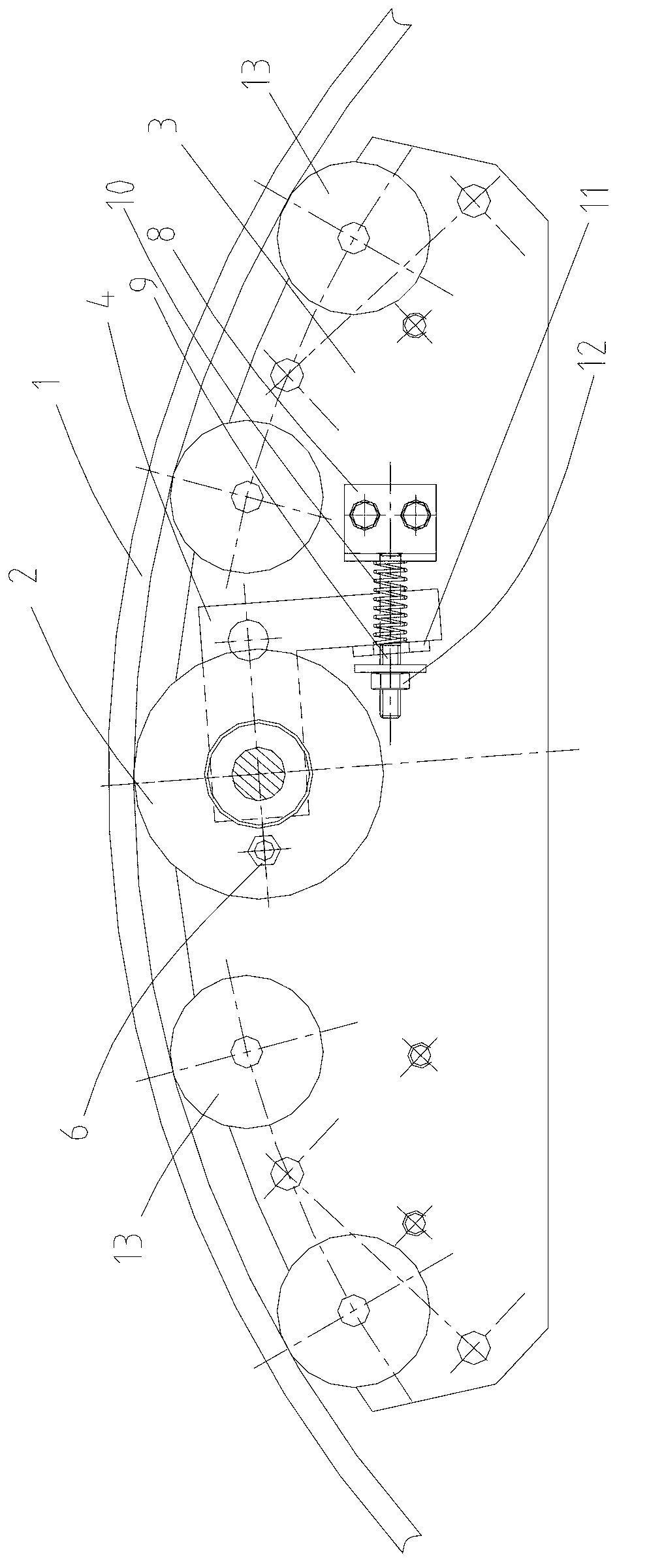
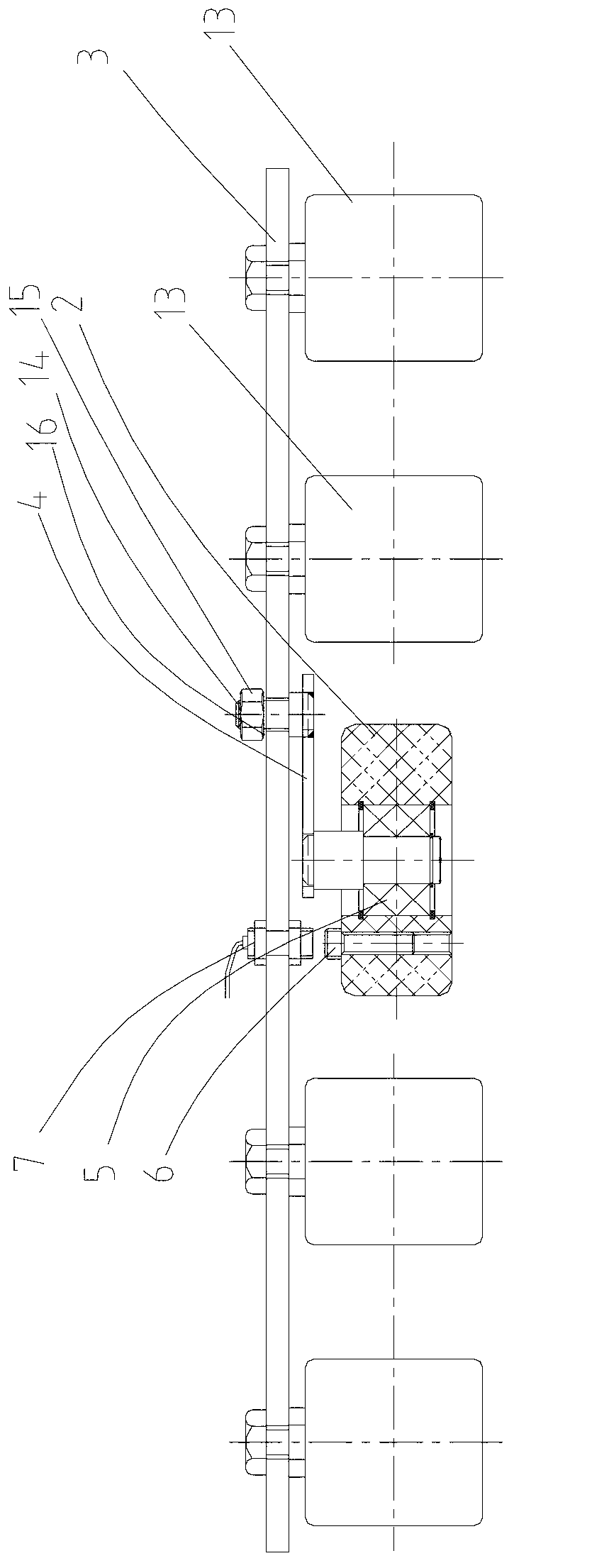
[0017] see Figure 1-2 As shown, a handrail speed measuring device for an escalator or a moving walk includes a fixed base plate 3, a non-metallic speed measuring wheel 2, a probe 7, and a support plate 4. Supporting rollers 13, a plurality of supporting rollers 13 support the handrail 1 through the wheel peripheral surface. Non-metallic speed measuring wheel 2 is contained on one end of support plate 4, in figure 1 Among them, the wheel peripheral surface of the non-metallic speed measuring wheel 2 is pressed by the handrail 1. When the handrail 1 is running, the speed measuring wheel 2 will be subjected to the friction force of the handrail 1 and roll synchronously. The surface of the non-metallic speed measuring wheel 2 is provided with Metal measuring point 6, such as figure 2 , the fixed base plate 3 is provided with a probe 7 capable of detec...


PUM


Abstract

The invention discloses a handrail strap speed measuring device of an escalator or a moving pavement, wherein a supporting plate is rotatablely arranged on a fixed bottom plate; a non-metal speed measuring wheel is arranged on an end part of the supporting plate; an elastic member is arranged between the other end part of the supporting plate and the fixed bottom plate; thus, when the speed measuring wheel operates on a tight side of the handrail strap, the speed measuring wheel is stressed by pressure of the handrail strap on the tight side to rotate downwards on the supporting plate and is prevented from being easily damaged due to overlarge stressing, and meanwhile, the handrail strap of the tight side is tightly pressed on a circumferential surface of the speed measuring wheel by means of elastic acting force of the elastic member; when the speed measuring wheel operates on a loose side of the handrail strap, the stressing of the speed measuring wheel is weakened, the speed measuring wheel rotates upwards on the supporting plate so that the handrail strap on the loose side can also be tightly pressed on the circumferential surface of the speed measuring wheel under the action of elastic restoring force of the elastic member, the height can be automatically adjusted by the speed measuring wheel according to an operation track of the handrail strap, and frictional operation of the handrail strap is guaranteed all the time to guarantee that a probe smoothly detects a signal and the escalator or the moving pavement can normally work; and the stress of the speed measuring wheel is not overlarge and the speed measuring wheel is not easily damaged.

Description

[0001] technical field [0002] The invention relates to a speed measuring device for a handrail of an escalator or a moving walk. [0003] Background technique [0004] When the escalator or moving walk is running, when the deviation of the running speed of the handrail from the actual speed of the steps or pedals exceeds the range specified by the standard, the handrail speed measuring device can stop the escalator or moving walk. The handrail speed measuring device usually adopts the metal measuring point on the non-metallic roller (or called the non-metallic speed measuring wheel), the electrical probe is set at a position very close to the metal measuring point, and the non-metallic roller is rolled synchronously by the friction force of the handrail , the electrical probe can detect the speed of the handrail. This device is simple and practical, but because the handrail is a flexible and flexible part, it has loose and tight sides in different running directions. Whe...

Claims


Application Information

Patent Timeline
Patent Type & Authority Applications(China)
IPC IPC(8): B66B25/00
Inventor 高静丹李春福张超蒋晓东
Owner SJEC CORP
Why Eureka
Try Eureka