Single-spindle drive wheel disc false-twist spinning device

A roulette and false twisting technology, applied in the direction of textiles and papermaking, can solve problems such as difficult additional installation and use of spinning frames, affect production management and overall benefits, reduce package capacity and production efficiency, and achieve improved false twist quality, The effect of shortening the length of the triangular area and simple structure

Active Publication Date: 2012-12-26
高密市元信纺织有限公司
View PDF7 Cites 10 Cited by
  • Summary
  • Abstract
  • Description
  • Claims
  • Application Information

AI Technical Summary

Problems solved by technology

The installation of additional drive mechanisms on the headstock and / or tailstock of the spinning frame with a compact space will affect the original design of the spinning frame, and the additional false twisting elements in the spinning section of each spindle will also affect the operation to a considerable extent, and may even make Reducing the spinning position or / and reducing the package capacity and other compromises that are not conducive to production efficiency, not only high investment and operation costs, but also affect production management and overall benefits
In particular, the surface friction rolling false twisting structure disclosed by the US2590374 US patent in 1949 requires additional long shafts, worms, worm gears and their fixing brackets in each spindle spinning section, which additionally occupies the original spinning space for specific purposes. space, it is difficult to install and use additionally on the existing spinning frame without compromise

Method used


Image

  • Single-spindle drive wheel disc false-twist spinning device
  • Single-spindle drive wheel disc false-twist spinning device
  • Single-spindle drive wheel disc false-twist spinning device

Examples


Embodiment Construction

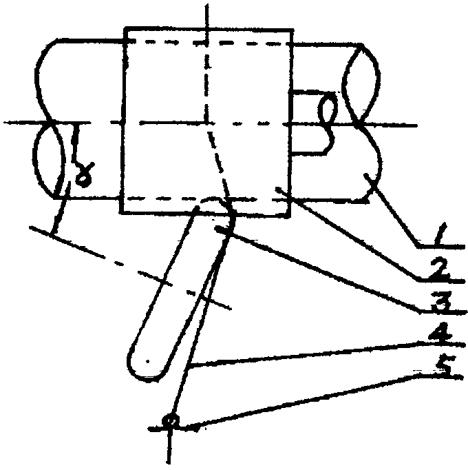
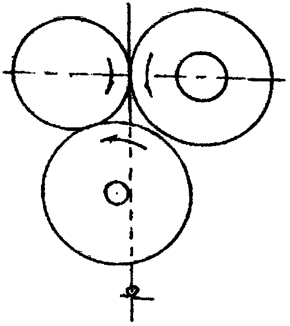
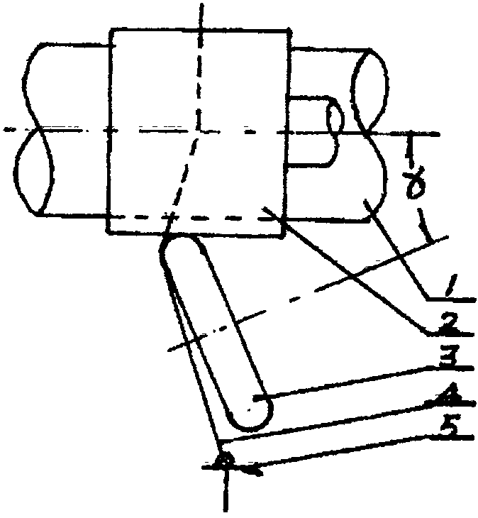
[0040] Single-spindle-driven disc false-twist spinning device uses a rotating disc as a false-twisting element, and the outer periphery of the rotating disc drives the yarn to rotate to generate false twisting. At least one false-twisting disc is installed downstream of the nip of the front roller. The outer circumference of the disc is in pressure contact with the front top roller or the front bottom roller, and the surface friction of the front top roller or bottom roller drives the wheel disc to rotate. There is an angle α between the axis of the wheel disc and the axis of the roller. The yarn output from the nip of the front roller is at least It has a false twist contact section with the outer periphery of a wheel.

[0041] The sliver drives the sliver to make the sliver roll around its own axis, so that the sliver obtains false twist.

[0042] The following examples all take the spinning of Z-twisted yarn as an example, and when spinning S-twisted yarn, the false twist e...


PUM

PropertyMeasurementUnit
radiusaaaaaaaaaa
widthaaaaaaaaaa
widthaaaaaaaaaa

Abstract

The invention provides a single-spindle drive wheel disc false-twist spinning device. A rotation wheel disc serves as a false-twist element, and the outer periphery of the rotation wheel disc drives a sliver in a frication mode to rotate so that false twist is generated. The single-spindle drive wheel disc false-twist spinning device is characterized in that the downstream of a front roller jaw is provided with at least one false-twist wheel disc, the periphery of one of the false-twist wheel disc contacts a front upper roller or a front lower roller in a pressing mode, the surface of the front upper roller or the front lower roller drives the false-twist wheel disc to rotate in a friction mode, the included angle alpha is formed between the axis of the false-twist wheel disc and the axis of the rollers is alpha, a false-twist contacting section exists between the sliver output from the front jaw and the periphery of at least one of the false-twist wheel discs.

Description

technical field [0001] The invention relates to the field of spinning equipment, and relates to a device for adding false twist in the spinning process of a ring spinning frame, in particular to a false twist spinning device using a wheel as a false twist element and a roller as a single spindle drive. Background technique [0002] During the spinning process of the ring spinning frame, the spinning process conditions and / or yarn properties have been improved by adding false twist to the spun sliver for decades. In the disclosed technology, the false twist device They are all set in the spinning section between the nip of the front roller and the yarn guide hook. The methods of mechanical false twisting are roughly divided into mechanical center friction drive, wheel surface friction rolling, double wheel disc or roulette group twisting, double-sided belt or belt set twisting, single-contact section dragon belt surface friction rolling, double contact section dragon belt sur...

Claims


Application Information

Patent Timeline
Patent Type & Authority Applications(China)
IPC IPC(8): D01H7/92
Inventor 陈子瑜
Owner 高密市元信纺织有限公司
Why Eureka
Try Eureka