
Method for simulating lightning trip-out rates of 500kV transmission line with four circuits on same tower
A technology of lightning tripping rate and simulation method, which is applied in the direction of measuring electricity, measuring electrical variables, measuring devices, etc., can solve problems such as increasing the cost of lines, affecting the safety and reliability of power grids, and making it difficult to ensure the accuracy of transmission lines. Achieve accurate calculation, improve safety and power supply reliability
- Summary
- Abstract
- Description
- Claims
- Application Information
AI Technical Summary
Problems solved by technology
Method used
Image

Examples
Embodiment Construction
[0015] In order to facilitate understanding of the present invention, the following will be described in conjunction with the accompanying drawings.
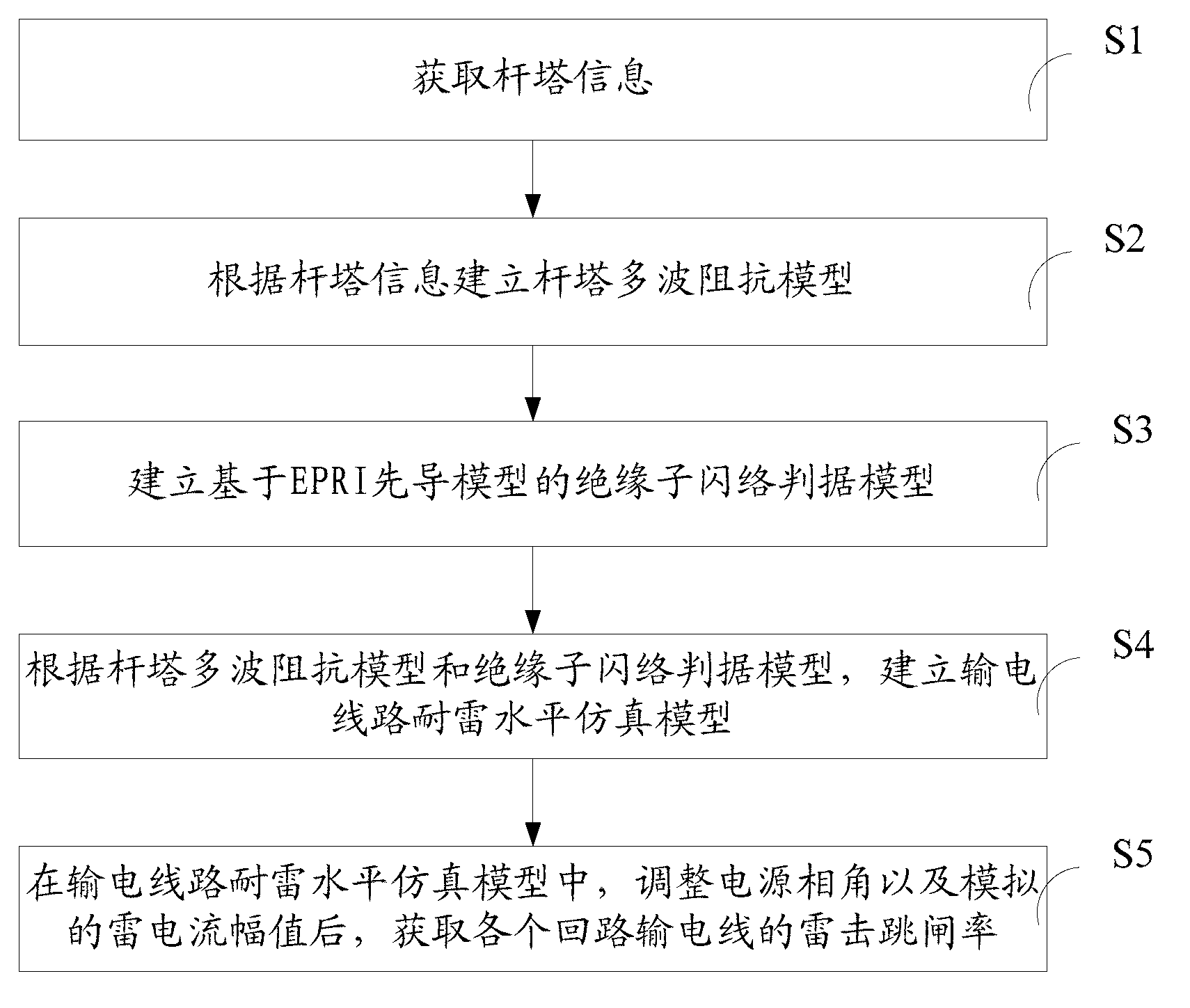
[0016] This invention proposes a simulation method for lightning tripping rate of 500kV four-circuit transmission line on the same tower, please refer to figure 1 , including steps:
[0017] S1. Obtain the tower information; wherein, the tower information includes: the height of the cross arm, the equivalent radius of the tower body, and the width of the cross arm;
[0018] S2. Establishing a tower multi-wave impedance model according to the tower information;
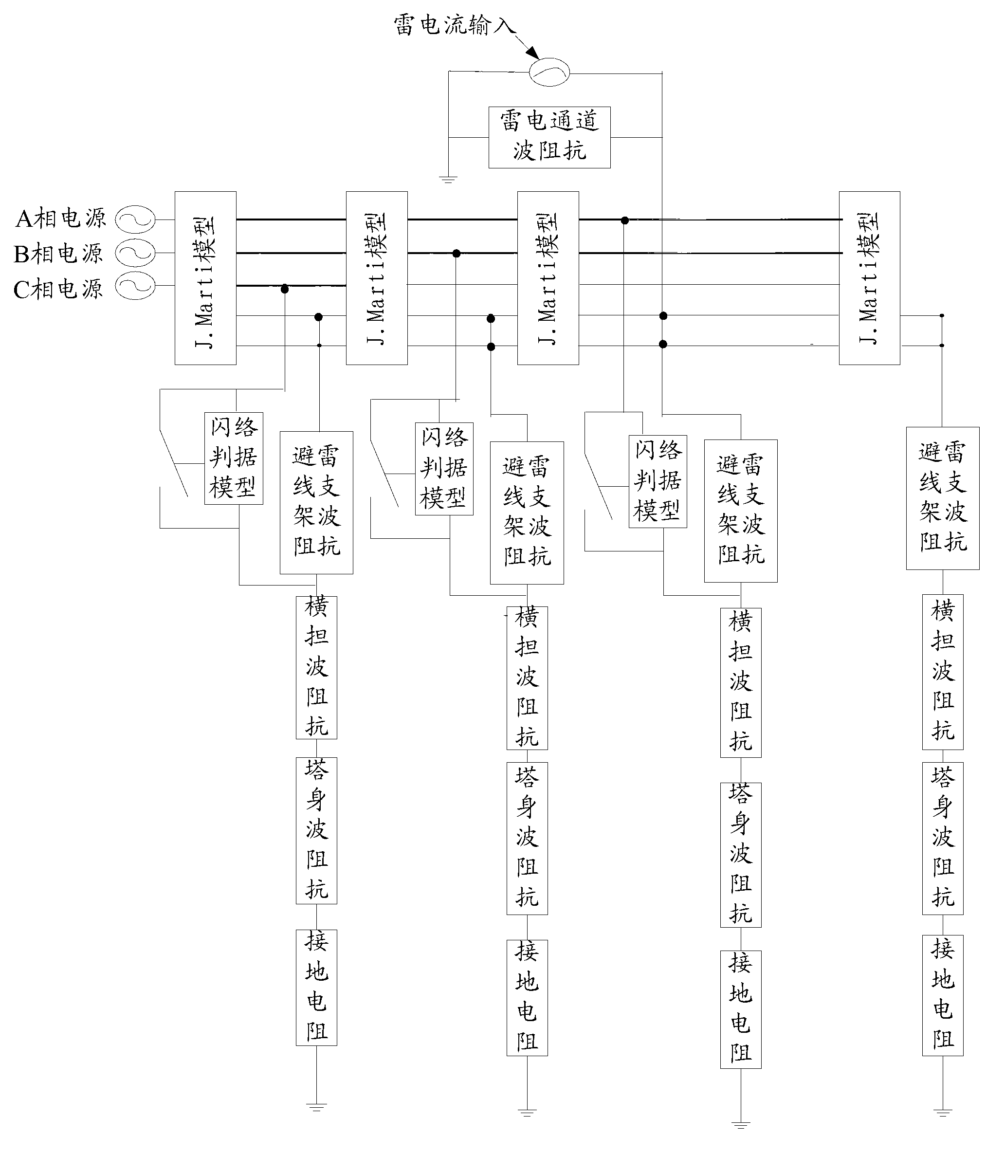
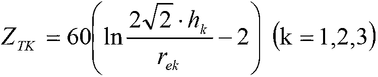
[0019] The multi-wave impedance model divides the tower into three parts: the tower body, the cross-arm, and the bracket, all of which are represented by wave impedance. For accurate calculation, each part is further refined into Multi-segment wave impedance; wherein, the step of establishing a tower multi-wave impedance model according to the tower information may inc...
PUM
 Abstract
Description
Claims
Application Information