Charging device and charging joint thereof

A charging device and contact technology, applied in circuit devices, battery circuit devices, current collectors, etc., to solve the problem of high cost, simplify the steps of opening or closing functions, and improve the convenience of assembly

Active Publication Date: 2014-11-05
INVENTECSHANGHAI TECH +2
View PDF4 Cites 0 Cited by
  • Summary
  • Abstract
  • Description
  • Claims
  • Application Information

AI Technical Summary

Problems solved by technology

There is a housing groove on the outside of the shell

Method used


Image

  • Charging device and charging joint thereof
  • Charging device and charging joint thereof
  • Charging device and charging joint thereof

Examples


Embodiment Construction

[0056] The embodiments of the charging device and its charging contacts according to the present invention will be described below with reference to the relevant figures. For ease of understanding, the same components in the following embodiments are described with the same symbols.

[0057] The electronic device mentioned in the present invention can be a personal action assistant (PDA), a rechargeable flashlight, a rechargeable battery, a mobile phone or various electronic devices that can be charged by the charging device. For the convenience of a better understanding of the technical characteristics of the present invention, The following uses a mobile phone as an example, but it is not limited thereto.

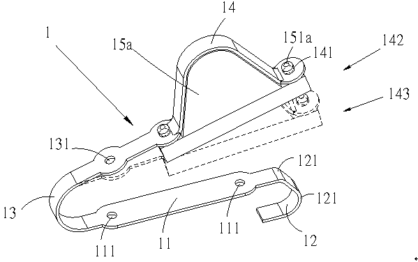
[0058] see figure 1 , which is a schematic diagram of an embodiment of the charging contact of the present invention. As shown in the figure, the charging contact 1 is formed integrally with a base material made of metal or metal alloy, and includes a fixing portion 11 ,...


PUM


Abstract

The invention discloses a charging device and a charging joint thereof. The charging joint comprises a fixing part, a conducting part, a U-shaped part, at least one shielding plate and a bearing plate, wherein the conducting part, which is extended from one end of the fixing part, is bent to form at least one arc part; the U-shaped part is extended from the other end of the fixing part in a bent manner; the U-shaped part and the conducting part are bent to two sides of the fixing part; the at least one shielding plate is arranged at the bearing part; the bearing part is extended from the U-shaped part; and when the bearing part is propped via an external force, the bearing part is shifted from a first position to a second position.

Description

technical field [0001] The present invention relates to a charging device and its charging contact, more particularly, to the field of improving the structure of the charging contact. Background technique [0002] At present, the charging contact of the general charging device is designed to have the function of reciprocating movement. When the electronic device is placed on the charging device, the charging contact can be displaced to contact and conduct the circuit to charge the electronic device. Some known charging contacts are made of elastic metal wires and arranged in the through holes of the charging device housing. Since the elastic metal wires are very thin, they are easy to see from the holes to the internal board. The appearance is not very beautiful and fashionable. Moreover, it is known that the charging contact is connected to the circuit board for a long time, and once a conductive foreign object falls into the gap of the through hole, the contact will be tu...

Claims


Application Information

Patent Timeline
Patent Type & Authority Patents(China)
IPC IPC(8): H02J7/00
Inventor 邱年伦
Owner INVENTECSHANGHAI TECH
Why Eureka
Try Eureka