Illumination device, display device, and television receiver

A technology for lighting devices and display devices, applied to lighting devices, components of lighting devices, lighting and heating equipment, etc., to achieve good display and excellent visual recognition

Inactive Publication Date: 2012-12-26
SHARP KK
View PDF7 Cites 7 Cited by
  • Summary
  • Abstract
  • Description
  • Claims
  • Application Information

AI Technical Summary

Problems solved by technology

In this way, there is still room for improvement in the development of backlight devices that suppress the occurrence of lamp images while suppressing power consumption.

Method used


Image

  • Illumination device, display device, and television receiver
  • Illumination device, display device, and television receiver
  • Illumination device, display device, and television receiver

Examples


Embodiment approach 1

[0080] use Figure 1 to Figure 7 Embodiment 1 of the present invention will be described.

[0081] First, the configuration of a television receiver TV including a liquid crystal display device 10 will be described.

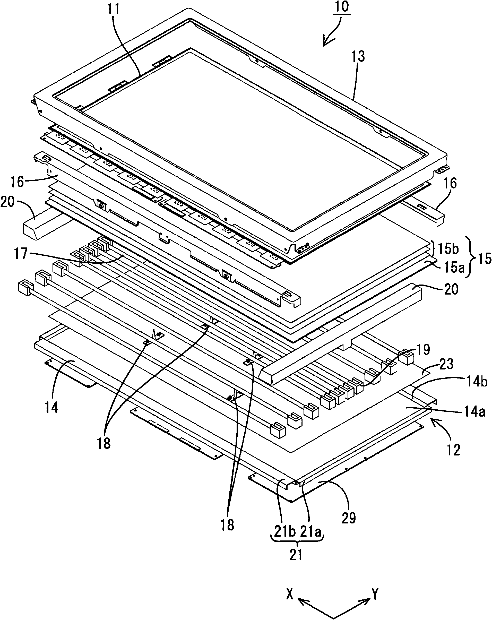
[0082] The television receiver TV of this embodiment is such as figure 1 As shown, it comprises a liquid crystal display device 10 , two front and back cases Ca, Cb, a power supply P, a tuner T, and a stand S sandwiching and accommodating the liquid crystal display device 10 . The liquid crystal display device (display device) 10 has a horizontally long rectangular shape as a whole, and is housed in a vertically placed state. The liquid crystal display device 10 such as figure 2 As shown, a liquid crystal panel 11 as a display panel and a backlight device (illumination device) 12 as an external light source are provided, and these are integrally held by a frame-shaped outer frame 13 or the like.

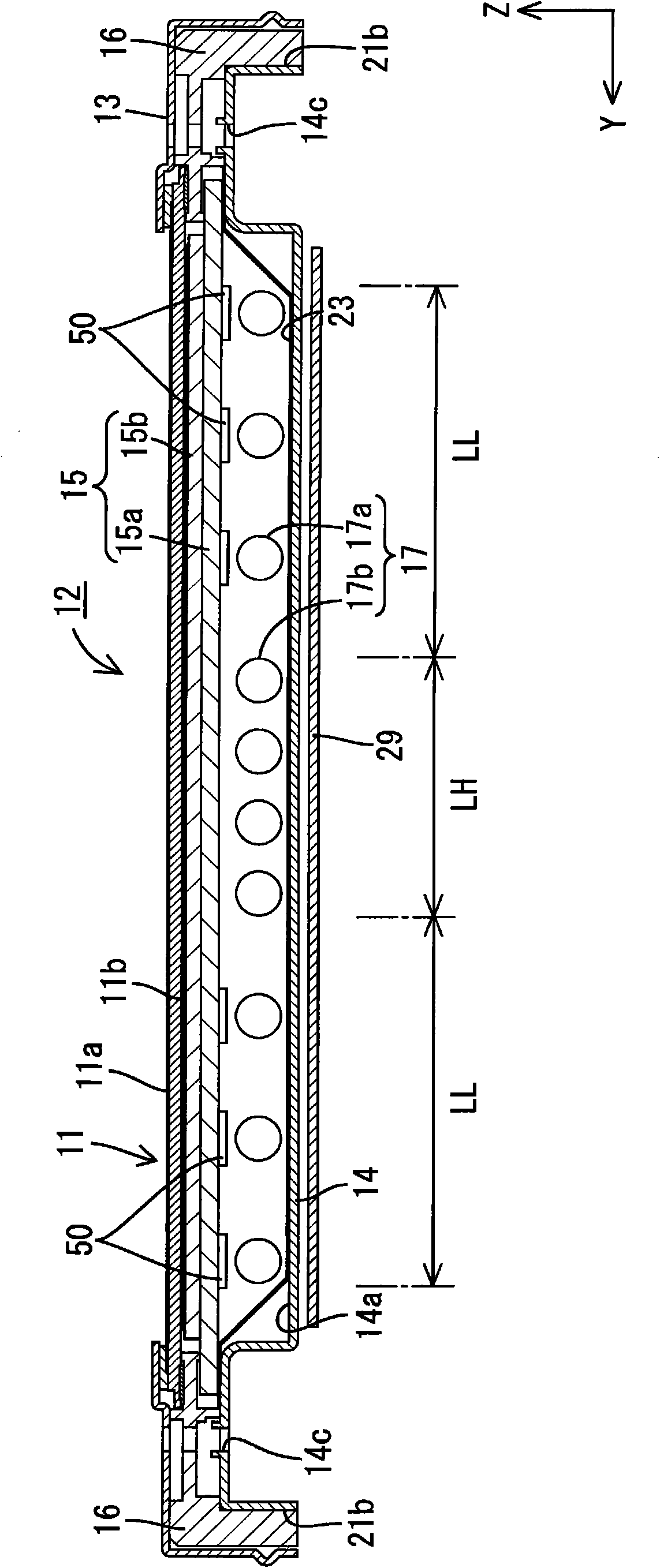
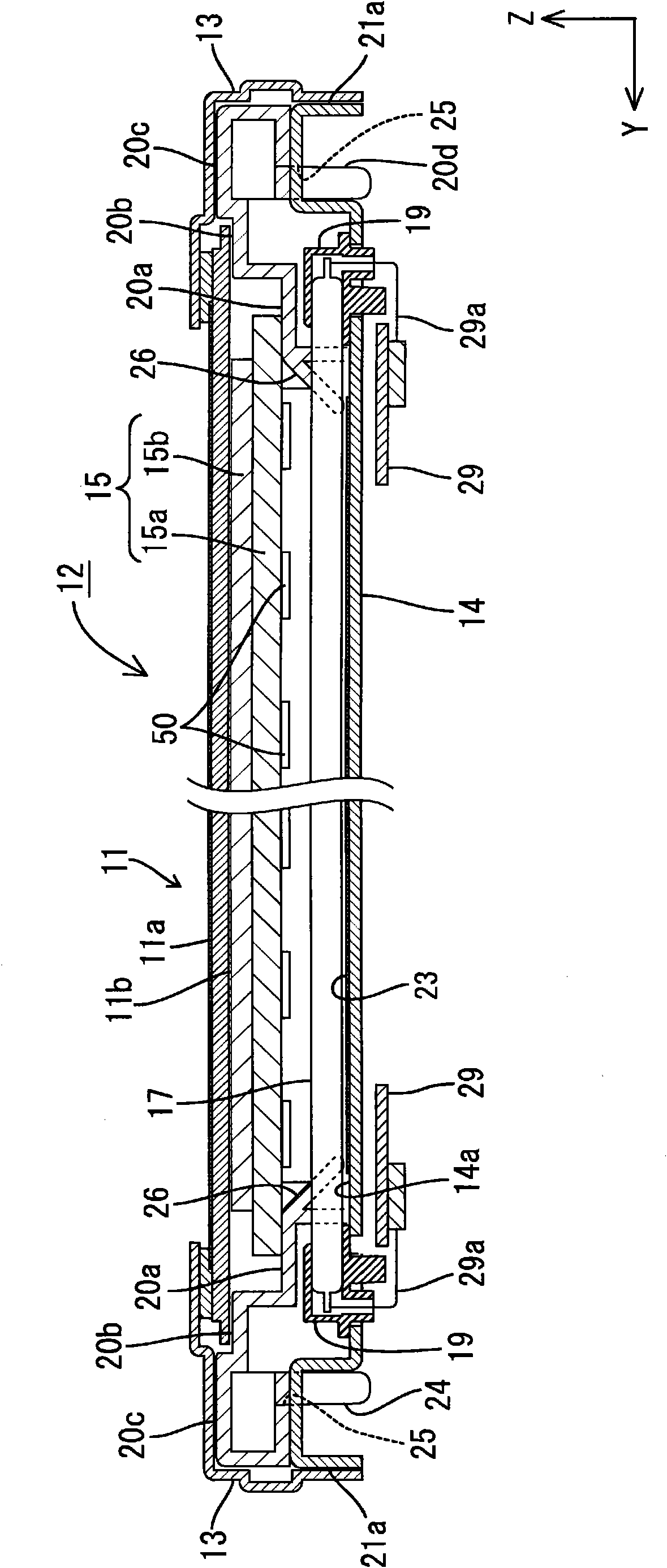
[0083] Next, the liquid crystal panel 11 and the backlight u...

Embodiment approach 2

[0122] Below, use Figure 10 to Figure 14 Embodiment 2 of the present invention will be described.

[0123] In the liquid crystal display device 10 included in the television receiver TV of the second embodiment, the light source is different from the light source of the first embodiment, and the others are the same as those of the first embodiment. The same reference numerals are assigned to the same parts as those in Embodiment 1, and repeated descriptions will be omitted.

[0124] The backlight unit 12 used in Embodiment 2 is, for example, Figure 10 As shown, an LED substrate (substrate) 81 is provided in the chassis 14 , and the LED substrate (substrate) 81 includes a point-shaped LED light source (point light source) 80 . The LED substrate 81 is a long thin plate-like member made of resin. The LED substrate 81 can be a flexible member such as a so-called LED tape, and can be fixed by a double-sided tape (not shown) or the like mounted on the back side (the side opposi...


PUM


Abstract

A lighting device achieves cost reduction and suppression of power consumption with suppressing the occurrence of a lamp image. A lighting device 12 includes: a plurality of linear light sources 17 disposed in parallel; a chassis 14 housing the linear light sources 17 and having an opening 14b through which light from the linear light sources 17 exits; and an optical member 15a facing the linear light sources 17 and disposed to cover the opening 14b. The linear light sources 17 are arranged at relatively small intervals in a light source high-density region LH and arranged at relatively large intervals in a light source low-density region. An optical member 15a includes a light reflection portion 50 configured to reflect light from the linear light sources 17 at least in a portion overlapping with the light source low-density region LL.

Description

technical field [0001] The present invention relates to an illuminating device, a display device and a television receiving device. Background technique [0002] For example, a liquid crystal panel used in a liquid crystal display device such as a liquid crystal television does not emit light by itself, and therefore requires a backlight device as an additional lighting device. It is well known that this backlight device is installed on the back side (the side opposite to the display surface) of the liquid crystal panel, and includes: a chassis having an opening in the surface on the liquid crystal panel side; a plurality of light sources (for example, cold cathode tubes) having It is housed in the chassis as a lamp, and an optical component (diffuser plate, etc.) is arranged in the opening of the chassis to efficiently emit light from the light source to the liquid crystal panel side. [0003] This backlight device adopts a configuration in which, when the light source emi...

Claims


Application Information

Patent Timeline
Patent Type & Authority Applications(China)
IPC IPC(8): F21S2/00F21V5/00F21V7/00G02F1/13357F21Y101/02F21Y103/00
CPCG02F1/133603G02F2001/133613G02F1/133605G02F1/133611G02F1/133613
Inventor 横田匡史
Owner SHARP KK
Why Eureka
Try Eureka