Dispersing device for solid particles

A solid particle and dispersing device technology, which is applied in the direction of solid separation, filter screen, grid, etc., can solve the problems of time-consuming and labor-intensive

Inactive Publication Date: 2013-01-02
CHINA PETROLEUM & CHEM CORP +1
View PDF3 Cites 3 Cited by
  • Summary
  • Abstract
  • Description
  • Claims
  • Application Information

AI Technical Summary

Problems solved by technology

At present, for solid particles with sizes ranging from millimeters to centimeters, manual dispersion is usually used, which is very time-consuming and labor-intensive

Method used


Image

  • Dispersing device for solid particles
  • Dispersing device for solid particles

Examples


Embodiment Construction

[0030] Specific embodiments of the present invention will be described in detail below in conjunction with the accompanying drawings. It should be understood that the specific embodiments described here are only used to illustrate and explain the present invention, and are not intended to limit the present invention.

[0031] In the present invention, under the situation of not stating to the contrary, the orientation words used such as "horizontal, vertical, upper layer, lower layer" etc. relate to the words of orientation, usually when the solid particle dispersing device provided by the present invention is placed on the horizontal plane normally defined when used.

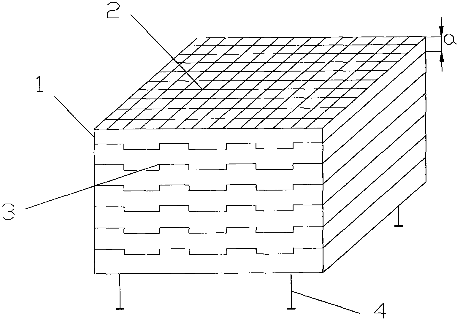
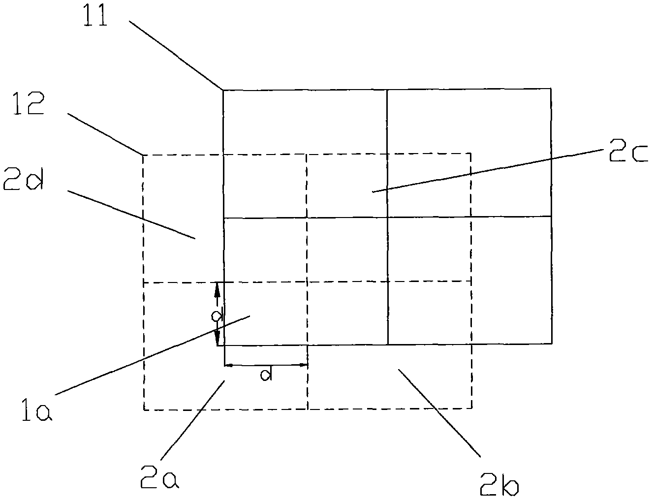
[0032] Such as figure 1 and figure 2 As shown, the present invention provides a solid particle dispersing device, which includes a plurality of sieve layers 1 spaced apart from each other in the vertical direction, and each sieve layer 1 is arranged with a plurality of sieve holes that allow solid particles ...


PUM

PropertyMeasurementUnit
Granularityaaaaaaaaaa

Abstract

The invention discloses a dispersing device for solid particles. The dispensing device comprises a plurality of screen layers (1) vertically arranged at an interval, a plurality of meshes (2) allowing the solid particles to pass are arranged on each screen layer (1), and the meshes (2) on adjacent screen layers (1) are mutually staggered vertically. The meshes (2) on adjacent screen layers (1) are mutually staggered, so that a plurality of different falling paths can be selected randomly according to shapes and sizes after the solid particles pass the top screen layer, finally the solid particles can fall below the dispersing device rapidly in a monolayer dispersing mode, and the dispersing device is simple in structure and high in practicability.

Description

technical field [0001] The invention relates to the field of solid particle processing, in particular to a solid particle dispersing device. Background technique [0002] Solid particles are common substances in fields such as industry and medicine, and they usually have different shapes depending on the type and scope of application. In the study of solid particles, computer image technology has a wide range of applications, such as microscope imaging technology, transmission electron microscopy technology and so on. With the development of computer application technology, image recognition has developed into an important application technology, which is widely used in various fields. [0003] The basic idea is to image solid particles through some instrument, and then use computer image processing technology to analyze and study their morphology. In the prior art, it is generally aimed at substances whose size is very small, such as those below 0.1 mm, which are difficul...

Claims


Application Information

Patent Timeline
IPC IPC(8): B07B1/04B07B1/46
Inventor 陈文斌龙湘云李明丰王奎刘学芬赵新强刘清河张乐聂红
Owner CHINA PETROLEUM & CHEM CORP
Why Eureka
Try Eureka