Method and device for jet/preoxidation/pyrolysis/fluidized bed gasification of carbon-containing solid fuel

A technology of fluidized bed gasification and fluidized bed gasification furnace, which is applied in the direction of manufacturing combustible gas, granular/powdered fuel gasification, petroleum industry, etc., and can solve the difficulty of dealing with caking coal and the technical difficulty of ash fusion problems such as large size and low carbon conversion rate, and achieve the effects of reducing the possibility of coking and coking, enhancing adaptability, and expanding the scope

Active Publication Date: 2011-07-13
INST OF PROCESS ENG CHINESE ACAD OF SCI
View PDF5 Cites 23 Cited by
  • Summary
  • Abstract
  • Description
  • Claims
  • Application Information

AI Technical Summary

Problems solved by technology

[0007] Among the above-mentioned fluidized bed gasifiers, the low-temperature Winkler gasifier has a relatively low carbon conversion rate because there is no recycled material, and the carbon content in the ash is relatively high; the KRW gasifier can handle caking coal, The carbon conversion rate is high, but it is difficult to use ash fusion technology, and the operation is difficult to be stable; the technology of Ende pulverized coal gasifier is mature and reliable, the operation is safe and stable, and the investment is small, but it is difficult to process caking coal, and the carbon conversion rate is low

Method used


Image

  • Method and device for jet/preoxidation/pyrolysis/fluidized bed gasification of carbon-containing solid fuel
  • Method and device for jet/preoxidation/pyrolysis/fluidized bed gasification of carbon-containing solid fuel
  • Method and device for jet/preoxidation/pyrolysis/fluidized bed gasification of carbon-containing solid fuel

Examples


Embodiment 1

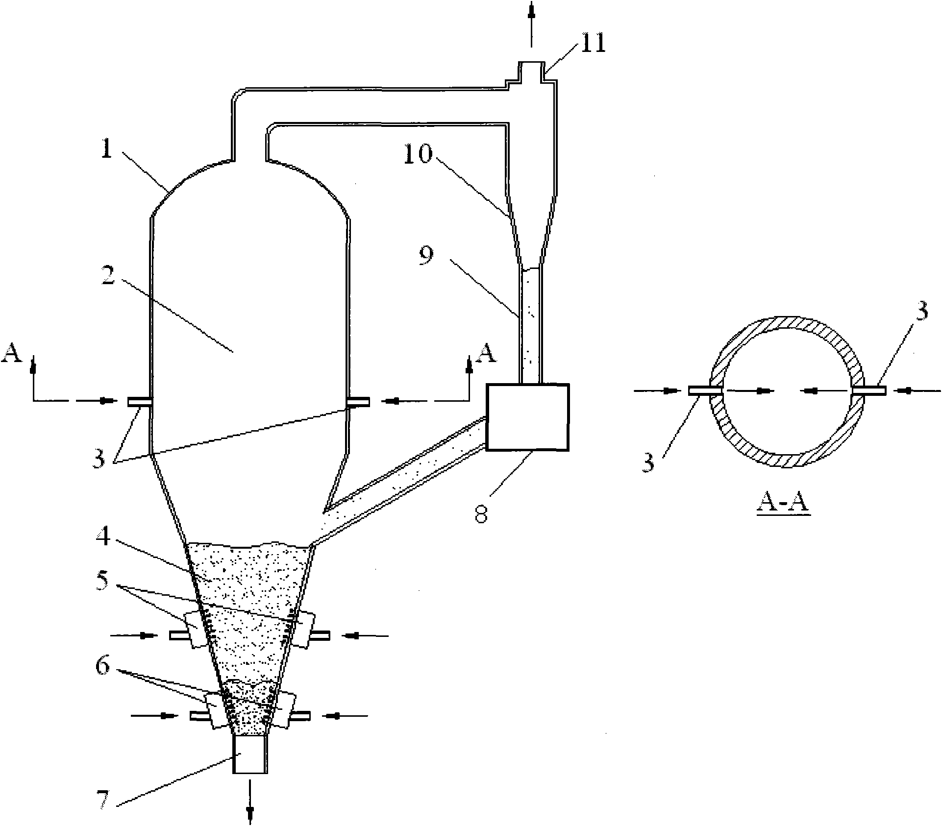
[0056] The jet flow pre-oxidation pyrolysis fluidized bed gasification device with two opposed fuel nozzles in this embodiment is as follows: figure 1 As shown, it mainly includes: fluidized bed gasifier 1, fluidized bed dilute phase zone 2, fuel nozzle 3, fluidized bed dense phase bed 4, oxygen-containing oxidizing agent first feeding system 5, oxygen-containing gasification Agent second feeding system 6, ash outlet 7, feeder 8, return pipe 9, cyclone separator 10 and crude gas or synthesis gas outlet 11.

[0057] There is an outlet on the top of the fluidized bed gasifier 1, which is connected to the material inlet of the cyclone separator 10 through a pipeline, and the material outlet of the cyclone separator 10 is connected to the inlet of the return pipe 9 The outlet of the return pipe 9 is connected with the inlet of the return device 8, and the outlet of the return device 8 is connected to the inlet provided on the lower furnace wall of the fluidized bed gasifier 1 thro...

Embodiment 2

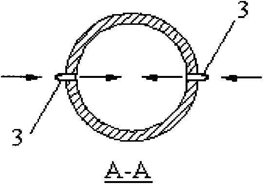
[0064] The jet flow pre-oxidation pyrolysis fluidized bed gasification device used in this embodiment is basically the same as that in Embodiment 1, except that two obliquely facing fuel nozzles are arranged upwards, and the hood is arranged obliquely downward. Its structure is as follows figure 2 shown. The oblique upward angle of the two obliquely facing fuel nozzles is 5-70 degrees (angle with the horizontal plane), and the installation direction of the wind cap is obliquely downward 30° with the horizontal plane

[0065] The method of jet pre-oxidation pyrolysis fluidized bed gasification of coal particles using the above-mentioned jet pre-oxidation pyrolysis fluidized bed gasification device with two obliquely facing upward fuel nozzles is roughly the same as that of embodiment 1, except that the fuel nozzle 3 The speed of the mixture of coal particles with a particle size below 3mm and the oxygen-containing oxidant should be within the range of 10-20m / s, and the gasific...

Embodiment 3

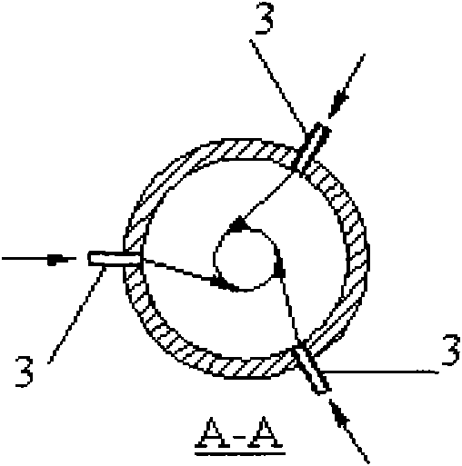
[0068] The jet flow pre-oxidation pyrolysis fluidized bed gasification device used in this embodiment is basically the same as that in Embodiment 1, except that three nozzles are evenly arranged in the furnace along the cross section of the above-mentioned gasification furnace at the lower part of the above-mentioned fluidized bed dilute phase zone 2. The direction of the fuel nozzle is deflected at the same angle and arranged in a tangential circle. Its structure is as follows image 3 shown. The method of jet pre-oxidation pyrolysis fluidized bed gasification of petroleum coke particles using the above-mentioned device is roughly the same as in Example 1.

[0069] The difference from Example 1 is that in the gasification process, petroleum coke particles are used as the gasification raw material, and the mixture of petroleum coke particles (below 6 mm in particle size) and gasification agent (oxygen) is injected from the three fuel nozzles 3 respectively. According to the s...


PUM

PropertyMeasurementUnit
particle diameteraaaaaaaaaa

Abstract

The invention belongs to the field of energy utilization of a solid fuel, and relates to a method and gasifier for jet/preoxidation/pyrolysis/fluidized bed gasification of a carbon-containing solid fuel. The method provided by the invention comprises steps as follows: by using oxygen-containing gasifying agent gas as a carrier, carbon-containing solid fuel particles are fed into a fluidized bed gasification furnace in a high-speed jet mode, so that the fuel particles are previously subjected to oxidation and pyrolysis in the high-speed jet and are highly dispersed; and the carbon-containing solid fuel particles are subjected to intensified pyrolysis in a dilute-phase region of the fluidized bed gasification furnace, and then, the formed semicokes of the carbon-containing solid fuel particles are moved into a dense-phase bed of the fluidized bed gasification furnace to participate in burning gasification reaction so as to generate crude gas or synthetic gas accompanied with fine semicoke particles and hot ash of the carbon-containing solid fuel. The method provided by the invention can be widely applied to various kinds of coal. The body of the fluidized bed gasification furnace ofthe jet/preoxidation/pyrolysis/fluidized bed gasification device is provided with fuel nozzles which are arranged at the circumference of the fluidized bed gasification furnace in an opposition, diagonal opposition or tangential circle mode.

Description

technical field [0001] The invention belongs to the field of high-efficiency energy utilization of solid fuels, and relates to a method and a gasification device for gasifying carbon-containing solid fuels in a jet-flow pre-oxidation pyrolysis fluidized bed, in particular to utilizing carbon-containing solid fuels in a fluidized bed gasification furnace The invention relates to a gasification method for producing carbon monoxide and hydrogen-based crude coal gas or syngas by injecting feed technology and a gasification device based on this method. The carbon-containing solid fuel gasification method and device can be applied to the gasification of various grades of coal including caking coal, biomass, petroleum coke and other carbon-containing solid wastes. Background technique [0002] Gasification refers to the use of carbon-containing fuels (coal, coal char or biomass, etc.) as raw materials, oxygen (air, oxygen-rich or industrial pure oxygen), water vapor or hydrogen as ...

Claims


Application Information

Patent Timeline
Patent Type & Authority Applications(China)
IPC IPC(8): C10J3/56C10J3/54C10J3/66C10J3/86C10J3/72
Inventor 董利张聚伟汪印田亚俊高士秋许光文
Owner INST OF PROCESS ENG CHINESE ACAD OF SCI
Why Eureka
Try Eureka