Shearing mechanism for lower chord steel bar of steel bar truss

A shearing mechanism and steel bar truss technology, applied in shearing devices, shearing machine equipment, metal processing equipment, etc., can solve the problems of asynchronous shearing, only one lower chord bar is cut, affecting the production of steel bar trusses, etc. The effect of structural stabilization

Inactive Publication Date: 2013-01-02
WUXI WEIHUA ELECTRIC WELDING MFG
View PDF5 Cites 4 Cited by
  • Summary
  • Abstract
  • Description
  • Claims
  • Application Information

AI Technical Summary

Problems solved by technology

[0004] In the prior art, the shearing cylinder is used to drive the power arm to rotate and cut off the two lower chord bars, but because the oil cylinder cannot be fixed, the shearing is sometimes out of sync, resulting in the phenomenon that only one lower chord bar is cut, which affects the production of steel trusses

Method used


Image

  • Shearing mechanism for lower chord steel bar of steel bar truss
  • Shearing mechanism for lower chord steel bar of steel bar truss
  • Shearing mechanism for lower chord steel bar of steel bar truss

Examples


Embodiment Construction

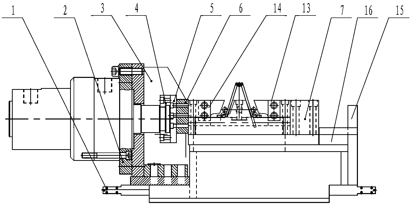
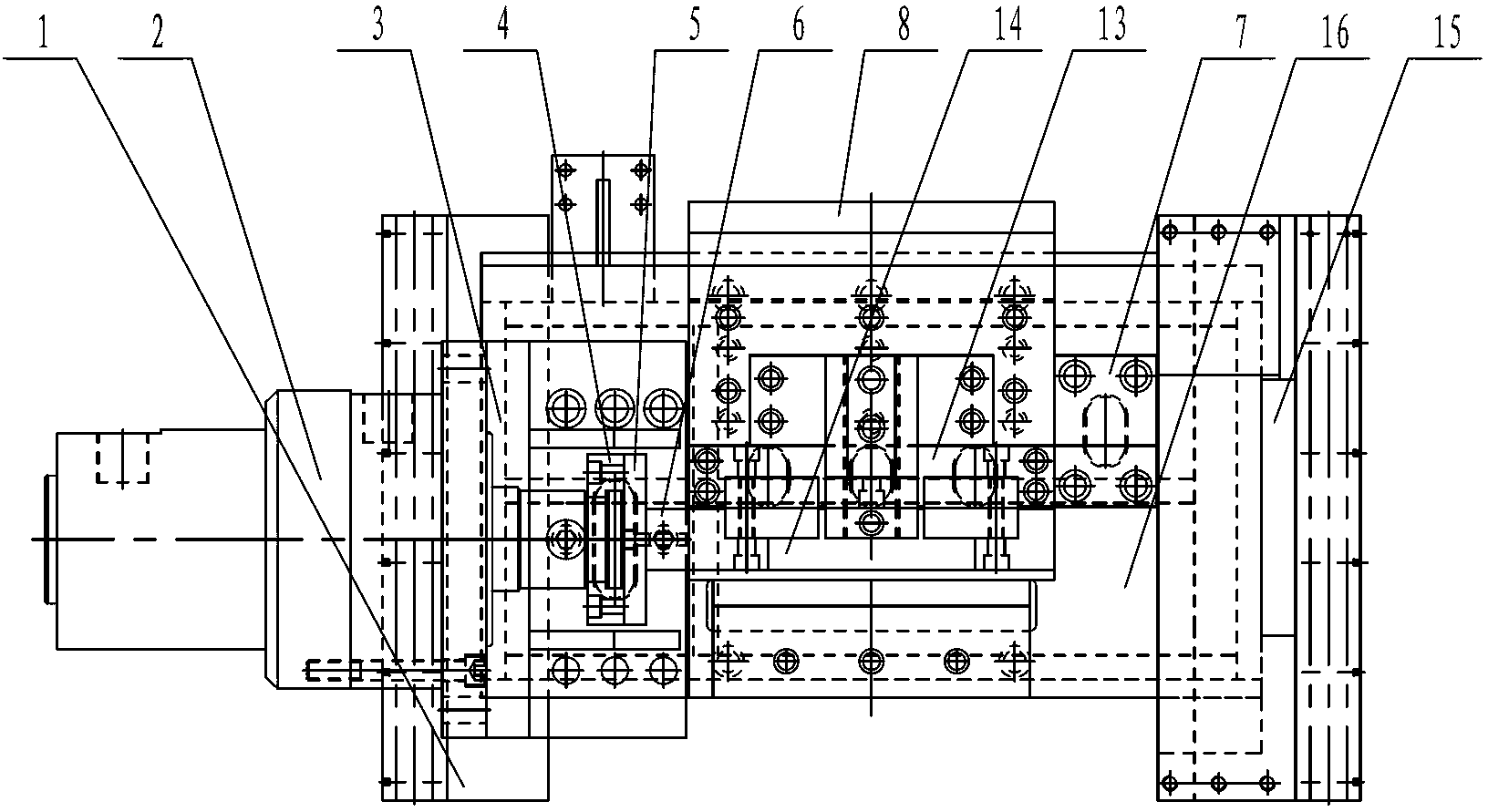
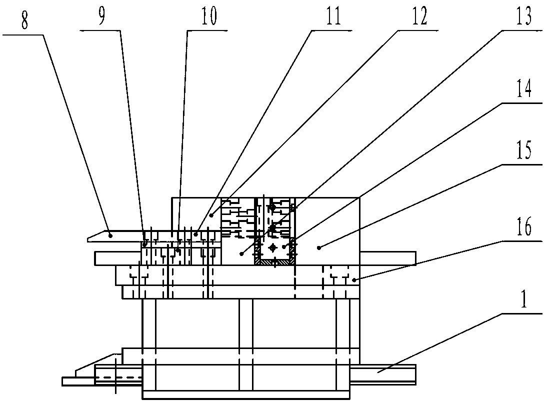
[0012] The specific embodiments of the present invention will be further described below in conjunction with the accompanying drawings.

[0013] Figure 1~Figure 3 Among them, including the lower frame 1, the lower shearing cylinder 2, the cylinder mounting frame 3, the half-moon cover 4, the connecting plate 5, the transition plate 6, the stopper 7, the guide plate 8, the adjusting plate 9, the lower backing plate 10, and the upper backing plate 11. Long fixed body 12, front tool seat assembly 13, rear tool seat assembly 14, limit block 15, large backing plate 16, etc.

[0014] Such as Figure 1~Figure 3 As shown, the present invention is a shearing mechanism for the lower chord bar of a steel bar truss, including a lower frame 1, a lower shear cylinder 2, a front knife block assembly 13 and a rear knife block assembly 14.

[0015] One side of the lower frame 1 is fixed with an oil cylinder mount 3 by screw keying, and the lower shear oil cylinder 2 is horizontally installe...


PUM


Abstract

The invention relates to a shearing mechanism for a lower chord steel bar of a steel bar truss. The shearing mechanism comprises an undercarriage, a lower shearing oil cylinder, a front knife holder component and a rear knife holder component, wherein an oil cylinder mounting frame is fixedly arranged on the undercarriage; the lower shearing oil cylinder is horizontally arranged on the oil cylinder mounting frame; a piston rod of the lower shearing oil cylinder is fixedly provided with the rear knife holder component; and the front knife holder component is fixedly arranged on the undercarriage and corresponds to the rear knife holder component in position. The lower shearing oil cylinder is horizontally and fixedly arranged on the undercarriage, the oil cylinder has a stable structure, and the piston rod of the oil cylinder does rectilinear motion, so that two steel bars can be easily sheared off without causing the phenomenon that one steel bar is not sheared off.

Description

technical field [0001] The invention relates to a steel truss bar truss welding production line, in particular to a steel bar truss lower chord bar shearing mechanism. Background technique [0002] The steel truss is spot-welded on the bottom plate to form a steel truss floor deck, which is used in industrial and civil buildings and structures. When it is used for concrete floor construction, it is laid on the beam to bear the concrete weight and construction load. At the same time, the steel truss is also Used as a permanent steel frame for the slab. [0003] Steel bar truss welding production line is a welding equipment production line that welds coiled steel bars into steel bar trusses. The steel truss mainly consists of one upper chord reinforcement (straight reinforcement), two lower chord reinforcements (straight reinforcement), and two web reinforcements (wavy). After the steel truss is welded to a certain length, these steel bars need to be cut off. [0004] In th...

Claims


Application Information

Patent Timeline
Patent Type & Authority Applications(China)
IPC IPC(8): B21F11/00B23D15/04B23D15/14
Inventor 吴克何静洁袁彬彬夏冬林林
Owner WUXI WEIHUA ELECTRIC WELDING MFG
Why Eureka
Try Eureka