Drill bit applied to machining process

A kind of mechanical processing and drilling technology, which is applied in the direction of metal processing equipment, drill repairing, drilling tool accessories, etc., can solve the problems of increasing chamfering process, increasing processing time, increasing workload, etc., so as to reduce processing steps and save tool change time , the effect of increasing the degree of

Inactive Publication Date: 2013-01-02
WUHU BETHEL AUTOMOTIVE SAFETY SYST
View PDF6 Cites 9 Cited by
  • Summary
  • Abstract
  • Description
  • Claims
  • Application Information

AI Technical Summary

Problems solved by technology

[0009] The technical problem to be solved by the present invention is that, in order to improve the processing efficiency, the drill bits in the prior art are often designed into a stepped shape, so as to achieve the effect of drilling and chamfering. The drill bits in the prior art generally use inc

Method used


Image

  • Drill bit applied to machining process
  • Drill bit applied to machining process
  • Drill bit applied to machining process

Examples


Embodiment Construction

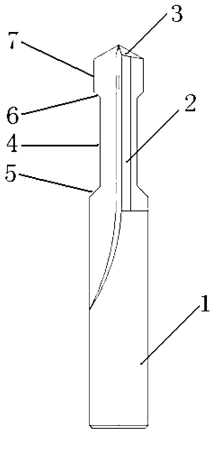
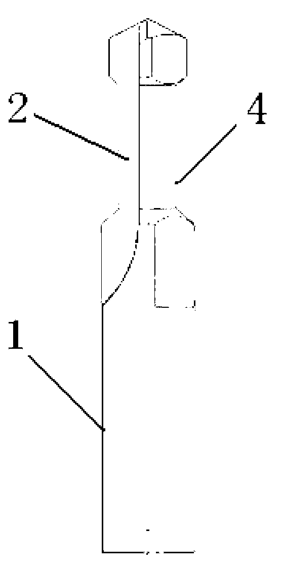
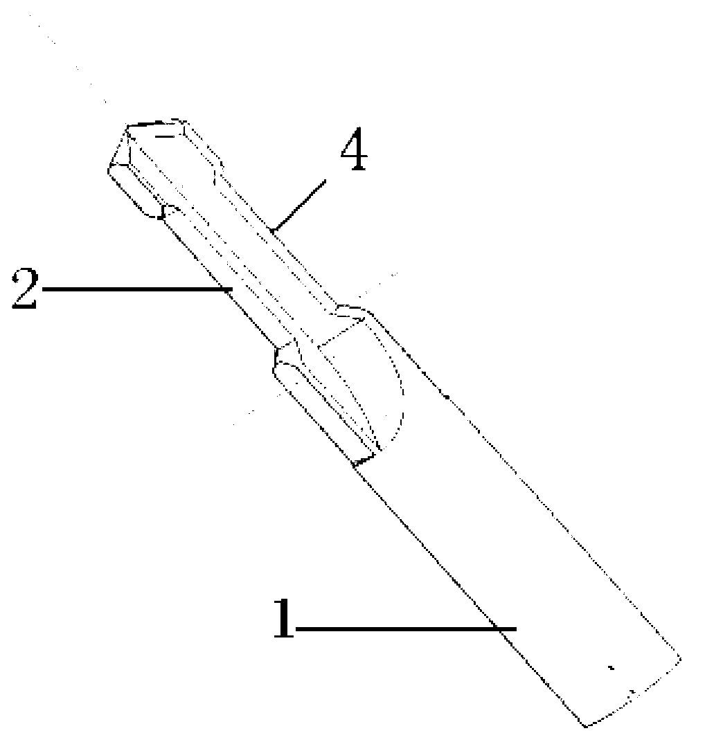
[0024] Such as Figure 1~3 As shown, the technical solution provided by the present invention is a chamfering drill applied in mechanical processing technology, including a drill shank 1, a drill body 2 and a drill tip 3, and the drill tip 3 is arranged on the drill body 2 The front end of the drill shank 1 is arranged at the rear end of the drill body 2, and the drill body 2 is provided with double chamfered cutting edges, and the chamfering directions of the double chamfered cutting edges are opposite. The drill body 2 is provided with a relief groove 4 , and the double-chamfered cutting edges are arranged at both ends of the relief groove 4 . The double chamfer cutting edge includes a forward chamfer cutting edge 5 and a reverse chamfer cutting edge 6, and the reverse chamfer cutting edge 6 is arranged at the front end of the sipe 4, that is, close to the drill tip 3 at one end. The forward chamfering cutting edge 5 is arranged at the rear end of the sipe 4 , that is, the...


PUM

PropertyMeasurementUnit
Diameteraaaaaaaaaa
Drilling depthaaaaaaaaaa

Abstract

The invention discloses a chamfering drill bit applied to a machining process. The chamfering drill bit comprises a drill stock, a drill body and a drill tip, wherein the drill tip is arranged at the front end of the drill body; the drill stock is arranged at the rear end of the drill body; the drill body is provided with double chamfer cutting edges; and chamfering directions of the double chamfer cutting edges are reverse. According to the technical scheme provided by the invention, a knife relieving groove is additionally arranged in a part of the drill body of a straight flue drill bit, and the chamfer cutting edges are additionally arranged at the two ends of the knife relieving groove, so that the knife replacing time is effectively saved, the effect of increasing the machining efficiency is obvious, a machining step of chamfering on a reverse face of the through hole is reduced, or the working load and the aesthetic measure brought by manual chamfering is removed, the degree of automatic machining is improved, and the three functions of drilling, chamfering on a front face of the hole and chamfering on a back face of the hole are realized.

Description

technical field [0001] The invention belongs to the technical field of manufacturing auxiliary production equipment in mechanical processing technology, and in particular relates to a drill bit used in mechanical processing technology. Background technique [0002] At present, the drill bit is the most common tool in mechanical processing, and its main function is to drill holes on relatively flat processing surfaces. [0003] There are various drill bit structures, and the common drill bit structures include the following structural forms, [0004] What is claimed is: 1. A drill bit comprising a shank having a tip with two cutting inserts lying on a main plane, the cutting inserts having short central cutting edges oriented on a common second plane. The cutting edge forms a point-shaped central cutting edge for entering the workpiece and thereby centering the drill bit. On the cutter bit shank, there are two flutes extending from the tip to the bottom. [0005] 2. A dril...

Claims


Application Information

Patent Timeline
IPC IPC(8): B23B51/08
Inventor 孔高松刘文明吴耀华
Owner WUHU BETHEL AUTOMOTIVE SAFETY SYST
Why Eureka
Try Eureka