Cutting machine with cutting clamp

A technology of clamping device and cutting machine, which is applied in the direction of shearing device, cutter for shearing machine, accessory device of shearing machine, etc., which can solve the problem of uneven cutting length and cutting weight, and the inability to produce blanks uniformly and constantly , Unable to stabilize the blank cutting accuracy and other problems, to achieve the effect of eliminating the rebound phenomenon, stably manufacturing parts, and uniform weight

Active Publication Date: 2016-08-17
MANYO
View PDF8 Cites 0 Cited by
  • Summary
  • Abstract
  • Description
  • Claims
  • Application Information

AI Technical Summary

Problems solved by technology

In this way, in the existing structure, since the state of making the bar close to the cutting knife and fixing it is not formed when cutting, it is impossible to avoid the rebound of the bar at the cutting position when cutting.
Therefore, the billet cannot be produced uniformly and constantly, and as a result, the cutting accuracy of the billet cannot be stabilized, and the cut length and cut weight are not uniform, resulting in a product lacking in uniformity

Method used


Image

  • Cutting machine with cutting clamp
  • Cutting machine with cutting clamp
  • Cutting machine with cutting clamp

Examples


Embodiment approach 1~3

[0058] according to Figure 6-8 Other embodiments 1 to 3 of the clamp cutting device will be described. In addition, in the description of these other embodiments 1 to 3, the same reference numerals are assigned to the same components as those in the above-mentioned embodiment, and detailed description thereof will be omitted.

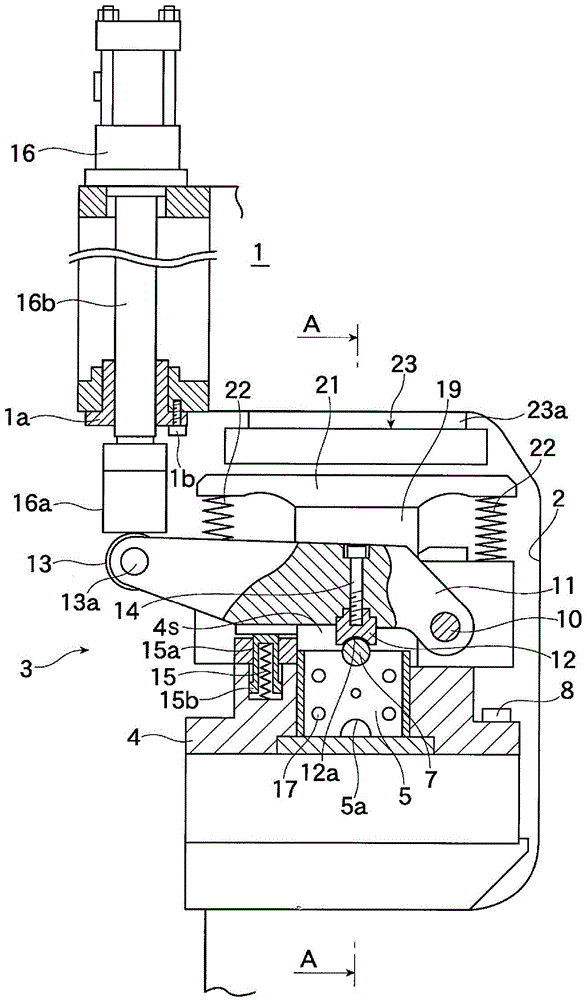
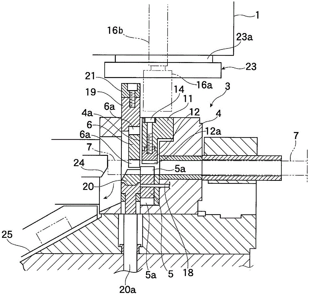
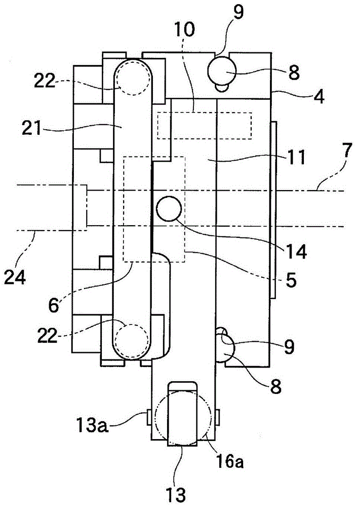
[0059] Figure 6 It shows the cutting machine provided with the cutting clamp device of other Embodiment 1, and is a front view which shows the rod-shaped cutting clamp device which provided the shaft body in the main body side. according to Figure 6 Another embodiment 1 of the clamp cutting device will be described.

[0060] In the above description, the case where the shaft body 10 as a fulcrum for swinging the lever 11 is provided on the base 4 has been described, but the shaft body 10 may be provided on the main body 1 side. Figure 6 as an example. The bearing member 26 is fixed to the wall surface of the recessed part 2 of the main body 1 ,...


PUM


Abstract

The invention provides a cutting machine provided with a cutting and clamping device. The cutting machine provided with the cutting and clamping device can prevent the bounce of a bar in cutting, thereby improving the cutting precision. The cutting machine provided with the cutting and clamping device is provided with a fixing cutter (5) and a movable cutter (6) cutting a delivered bar (7) and utilizes the shear force of the fixed cutter and the movable cutter to cut off the bar. A base is arranged on the cutting machine is a dismountable manner. The fixed cutter (5) having a cutter part (5a) capable of reversing for charging and the movable cutter (6) moving relatively to the fixed cutter are arranged on the base. A press component (12) is arranged to dispose in a position opposite to the fixed cutter over the bar. The press component (12) is used for pressing an opposite side of a fixed cutter side of the bar when cutting the bar. The press component (12) swings up and down because of the swing of the rod (11) and press and clamp the bar (7) through the driving the hydraulic pressure cylinder (16) when cutting.

Description

technical field [0001] The present invention relates to a cutting machine provided with a cutting clamp that presses and cuts a rod. More specifically, it relates to a cutting machine provided with a cutting clamp device which is installed in a cutting machine which cuts a bar material by shearing, and which presses and cuts a bar delivered to a fixed knife in order to manufacture a billet. bar. Background technique [0002] In order to manufacture forged workpieces (forgings) as metal parts, it is first necessary to cut from a rod-shaped billet with a specified size (for example, a round-shaped, polygonal-shaped billet with a specified size, hereinafter referred to as a bar) as its blank. into a volume equivalent to the required component of one part unit thereof. In other words, what is called a blank (metal sheet, steel sheet) having the desired length must be obtained by cutting from the bar. There are various methods for obtaining the blank, but one of them is punch ...

Claims


Application Information

Patent Timeline
Patent Type & Authority Patents(China)
IPC IPC(8): B23D15/04B23D33/02
CPCB23D15/04B23D33/08B23D35/001
Inventor 盐川博康
Owner MANYO
Why Eureka
Try Eureka