Clamp for milling spiral groove on surface of shaft type work piece

A shaft workpiece and spiral groove technology is applied in the field of fixtures for milling spiral grooves on the surface of shaft workpieces. , the effect of reducing the milling time

Inactive Publication Date: 2013-01-02
SUZHOU CITY JIANJUN TEXTILE MACHINERY PARTS FACTORY
View PDF0 Cites 4 Cited by
  • Summary
  • Abstract
  • Description
  • Claims
  • Application Information

AI Technical Summary

Problems solved by technology

Compared with lathes, using a milling machine to mill spiral grooves is more efficient and has a wider range of use. The milling cutter can reach a larger cutting depth in one feed. However, when using a milling machine to mill spiral grooves on the surface of shaft workpieces, milling Difficulty, long milling time and high milling cost, difficult to guarantee milling accuracy, not suitable for batch processing

Method used


Image

  • Clamp for milling spiral groove on surface of shaft type work piece
  • Clamp for milling spiral groove on surface of shaft type work piece

Examples


Embodiment Construction

[0013] The present invention is described below in conjunction with accompanying drawing.

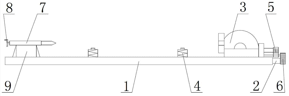
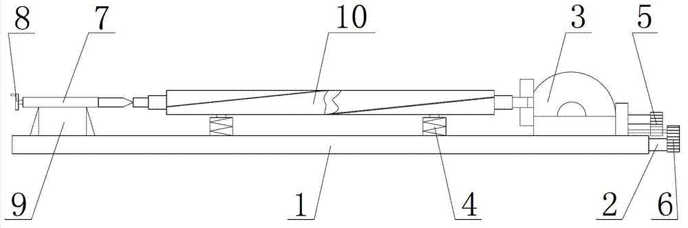
[0014] as attached figure 1 The shown fixture for milling a spiral groove on the surface of a shaft workpiece according to the present invention includes a milling machine table 1, a screw rod 2 is arranged inside the milling machine table 1, and a universal indexing device is provided at one end of the milling machine table The head 3 and the other end are provided with a positioning tailstock; the universal indexing head 3 and the positioning tailstock are located on the same horizontal line; the milling machine table 1 is provided with an automatic adjustment shock absorber 4; the automatic adjustment shock absorber The device 4 is located between the positioning tailstock and the universal indexing head 3; the outer end of the universal indexing head 3 is provided with a slave gear 5; the screw mandrel 2 is provided with a master gear 6 cooperating with the slave gear 5; The positi...


PUM


Abstract

The invention discloses a clamp for milling a spiral groove on the surface of a shaft type work piece. The clamp comprises a milling machine table, wherein one end of the milling machine table is provided with a universal indexing head, and the other end of the milling machine table is provided with a locating tailstock; the universal indexing head and the locating tailstock are located at the same horizontal straight line; the milling machine table is provided with self-regulating dampers; the self-regulating dampers are located between the locating tailstock and the universal indexing head; the locating tailstock comprises a centre, a crank and a base; the base is arranged on the milling machine table; the base is provided with the centre; the centre is connected with the crank; and the number of the self-regulating dampers is two. The clamp for milling the spiral groove on the surface of the shaft type work piece disclosed by the invention is simple to operate, and can reduce milling difficulty so as to reduce milling time and milling cost; the clamp is suitable for batch machining; and the self-regulating damper can effectively reduce the vibration caused by the contact of the shaft type work piece and a tool, thus improving milling precision.

Description

technical field [0001] The invention relates to a fixture, in particular to a fixture for milling a spiral groove on the surface of a shaft workpiece. Background technique [0002] At present, in principle, the machining of the spiral groove on the surface of the shaft workpiece can be done by rotating the workpiece and feeding the tool in the axial direction, or by rotating the workpiece and feeding in the axial direction while the tool works. Compared with lathes, using a milling machine to mill spiral grooves is more efficient and has a wider range of use. The milling cutter can reach a larger cutting depth in one feed. However, when using a milling machine to mill spiral grooves on the surface of shaft workpieces, milling Difficulty, long milling time and high milling cost, difficult to guarantee milling accuracy, not suitable for batch processing. Contents of the invention [0003] In view of the above-mentioned technical problems, the object of the present invention...

Claims


Application Information

Patent Timeline
Patent Type & Authority Applications(China)
IPC IPC(8): B23Q1/25B23Q3/00
Inventor 翁杏根
Owner SUZHOU CITY JIANJUN TEXTILE MACHINERY PARTS FACTORY
Why Eureka
Try Eureka