Device for automatically propelling screw into pipe

A screw and automatic technology, applied in screwdrivers, wrenches, manufacturing tools, etc., to achieve the effect of improving construction efficiency and broadening market space

Inactive Publication Date: 2013-01-02
曹文渊
View PDF0 Cites 5 Cited by
  • Summary
  • Abstract
  • Description
  • Claims
  • Application Information

AI Technical Summary

Problems solved by technology

[0004] The problem to be solved by the present invention is the deficiency that the existing electric screwdriver screws need to be taken by hand

Method used


Image

  • Device for automatically propelling screw into pipe
  • Device for automatically propelling screw into pipe
  • Device for automatically propelling screw into pipe

Examples


Embodiment Construction

[0014] The present invention will be further described below in conjunction with the accompanying drawings and embodiments.

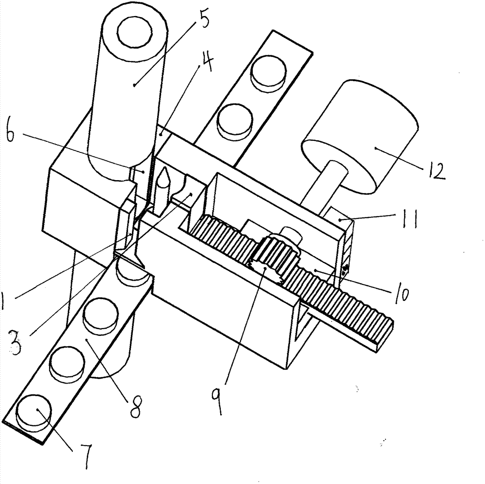
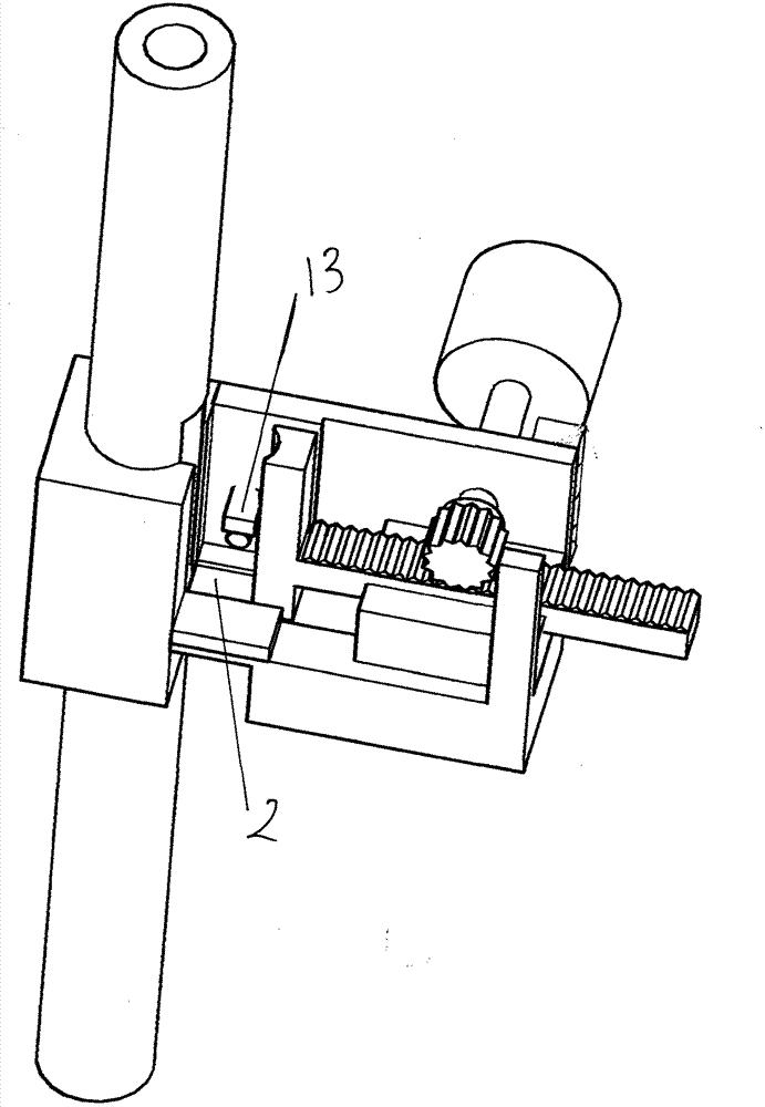
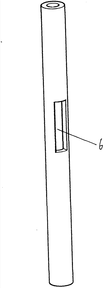
[0015] A screw automatic pipe insertion device, including dovetail groove 1, groove 2, concave semicircular block 3, fixing seat 4, screw feeding pipe 5, window 6, magnet 7, belt 8, rack and pinion mechanism 9, slide rail mechanism 10. Control system 11, motor 12 and sensor 13, the screw tube 5 is inserted into the through hole of the fixing seat 4, one side of the fixing seat 4 is provided with a dovetail groove 1, and the other side is provided with a sensor 13; the screw tube 5 is provided A window 6 is opened on the top, and its size is equivalent to the cross-sectional size of the screw, so that the screw can enter loosely; a groove 2 is provided on the fixing seat 4 facing the window 6, so that after the screw enters the groove 2, it reaches the position facing the window 6 , so that the concave semicircular block 3 pushes the screw into the screw...


PUM


Abstract

The invention discloses a device for automatically propelling a screw into a pipe and belongs to the field of tools. The device comprises a dovetail groove, a groove, a concave semicircular block, a fixed seat, a screw propelling pipe, a window, a magnet, a belt, a gear and rack mechanism, a sliding rail mechanism, a control system, a motor and a sensor, wherein the screw propelling pipe is inserted into a through hole of the fixed seat; the dovetail groove is formed in one side of the fixed seat; the sensor is arranged on the other side of the fixed seat; the window is formed in the screw propelling pipe; the groove is formed in the fixed seat opposite to the window in position; the sliding rail mechanism is arranged in a cavity of the fixed seat; the gear and rack mechanism is arranged on the sliding rail mechanism; the concave semicircular block and the motor are arranged on the gear and rack mechanism; the magnet is arranged on the belt; and the control system is arranged on the side wall of the fixed seat. According to the device, a reciprocating mechanism formed by the sliding rail mechanism is powered by the motor, the gear and the rack by using an automatic control system; the concave semicircular block for propelling the screw moves towards the screw propelling pipe so as to automatically propel the screw to the inside of the screw propelling pipe, and thus the automatic feed of the screw is realized.

Description

technical field [0001] The invention relates to a screw automatic tube insertion device, which belongs to the field of tools. Background technique [0002] When current electric screwdrivers use screws, the screws are taken by hand. In order to realize automatic screw feeding, it is a necessary process to automatically enter the screw into the screw feeding tube. Therefore, how to realize that the screw automatically enters the screw tube is an urgent problem to be solved. Contents of the invention [0003] The purpose of the present invention is to provide a screw automatic pipe insertion device. [0004] The problem to be solved by the present invention is the deficiency that the existing electric screwdriver screws need to be taken by hand. [0005] For realizing the purpose of the present invention, the technical scheme that the present invention adopts is: [0006] An automatic screw pipe feeding device, including dovetail groove, groove, concave semicircular bloc...

Claims


Application Information

Patent Timeline
Patent Type & Authority Applications(China)
IPC IPC(8): B25B23/04
Inventor 曹文渊
Owner 曹文渊
Why Eureka
Try Eureka