Train laser safety guidance method

A train and laser technology, applied in the direction of railway signal and safety, railway car body parts, vehicle control route devices, etc., can solve the problems of undetectable obstacles, land subsidence, broken bridges, etc.

Inactive Publication Date: 2015-07-29
梁衍庆
View PDF4 Cites 0 Cited by
  • Summary
  • Abstract
  • Description
  • Claims
  • Application Information

AI Technical Summary

Problems solved by technology

However, the method of satellite navigation and driving in the blocked section can only prevent the rear-end collision of the train and cannot detect obstacles, land subsidence, and broken bridges caused by heavy rain, earthquakes or human beings, and detect obstacles, land subsidence, and broken bridges. Stop or brake the train automatically
The method of directly monitoring the railway with cameras may also be affected by unfavorable factors such as rain, heavy fog, and night, which may cause dispatchers and drivers to fail to detect abnormalities in time. These situations are very dangerous

Method used


Image

  • Train laser safety guidance method
  • Train laser safety guidance method
  • Train laser safety guidance method

Examples


Embodiment 1

[0031] This embodiment is to illustrate how "the laser directly or uses the laser and the light control switch to irradiate the corresponding light control switch in a zigzag line" is how to detect obstacles, subsidence, broken bridges or trains on the railway and automatically and safely control the train of.

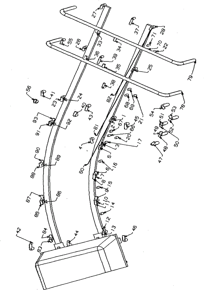
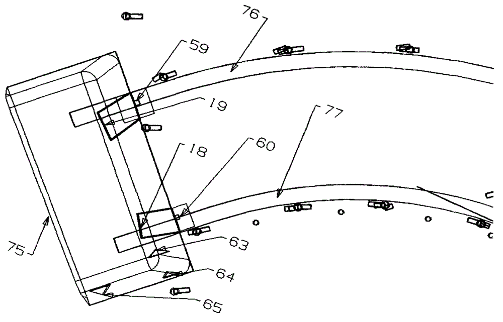
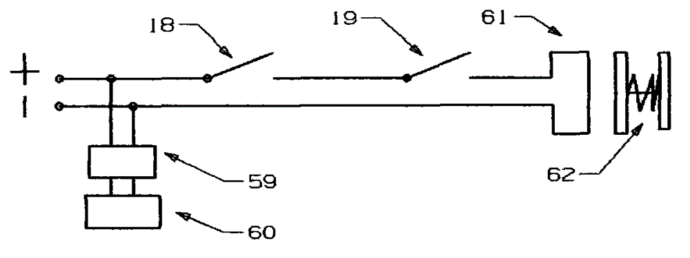
[0032] The "laser directly irradiates the corresponding optical switch" mentioned above (see figure 1 , figure 2 , image 3 , Figure 6 ) is that when the train goes to the laser device 66 position, push 66 to the left with the switch push block 63 to turn on the laser device 55, then 55 shines on 56, and 56 opens the traction laser device 26, 25 of its corresponding detection road section in a series connection mode, and then 26 and 25 shine on the light control switches 18 and 19 on the train respectively, then 18 and 19 open the relay 61 in a series connection mode, and then 61 presses the train start button 62 with thrust to start the train, if there is a gap b...

Embodiment 2

[0035] This embodiment is to illustrate how to use the detection method of "the laser uses the laser and the light control switch to sequentially irradiate the corresponding light control switch in a zigzag line" so that the train can detect the previous section of the road when the railway turns, goes uphill, and goes downhill. Obstacles or trains on the rails. see figure 1 , figure 2 , image 3 , Figure 4 , Figure 5 , Figure 6 When the train 75 goes to the position of the light control switch 46 and there are 1,500 meters, the switch push block 63 switches the switches of the lasers 41, 43, 45 (this switch has no picture in the accompanying drawings but it has the same principle as the laser switch 66) Same) Push to the left to turn on the lasers 41, 43, 45, then 41, 43, 45 illuminate the light control switches 42, 44, 46 respectively, then 42, 44, 46 turn on the traction lasers 2, 23 and the lasers in series connection 1, 24, then 1, 24 shines on the light control...

Embodiment 3

[0037] This embodiment is to illustrate how the train is used in combination with the principles of the above embodiments. Figure 6 The switching sequence and circuit connection method of "turn on the laser of the second detection section before the train - turn off the laser of the first detection section before the train - turn on the relay and push the laser switch of the third detection section after the train to the right to return to the original position" as shown It enables the train to detect obstacles, land subsidence, and broken bridges in the previous section of the journey in advance, and automatically and safely control the train and the train behind the interval to prevent rear-end collision accidents. see figure 1 , figure 2 , image 3 , Figure 6 , when the train travels to the laser switch 66 position, the switch push block 63 pushes 66 to the left to open the lasers 55, 39, 54 of the second detection section before the train, and then 55, 39, 54 shine on...


PUM


Abstract

The invention discloses a simple and reliable train laser safety guiding method which is characterized in that an optically-controlled switch can be shielded by an object capable of avoiding interference of an light source except a corresponding laser. Continuous irradiation is performed through the corresponding laser directly or a laser and the optically-controlled switch in zigzag line arrangement. A traction laser at a corresponding detection section is started by corresponding optically-controlled switches in series mode, an optically-controller switch on a train is irradiated by the traction laser so as to start a relay, and a train starting button is pressed so as to start up the train. The train can detect barriers, trains, broken bridges, land subsidence at a front journey in advance by combining a circuit connecting method shown in a picture 6, and the train laser safety guiding method can control the train safely and automatically and has an interval with a behind train so as to prevent tailgating. Simultaneously, lasers and optically-controlled switches for detection all day long are installed at the whole journey in addition. When the optically-controlled switches cannot sense laser due to abnormal conditions, corresponding cameras can be opened rapidly, and videos are uploaded so as to enable dispatchers and drivers to monitor abnormal sections on purpose.

Description

technical field [0001] The invention relates to a train safe running method, a railway safety monitoring method and a railway safety device. Background technique [0002] At present, the railway department mainly uses satellite navigation and the method of driving in blocked sections to prevent trains from rear-end collisions and monitors abnormal conditions of the railways with cameras to ensure safe running of trains. However, the method of satellite navigation and driving in the blocked section can only prevent the rear-end collision of the train and cannot detect obstacles, land subsidence, and broken bridges caused by heavy rain, earthquakes or human beings, and detect obstacles, land subsidence, and broken bridges. Make the train stop or brake automatically. The method of directly monitoring the railway with cameras may also be affected by unfavorable factors such as rain, heavy fog, and night, which may cause dispatchers and drivers to fail to detect abnormalities in...

Claims


Application Information

Patent Timeline
Patent Type & Authority Patents(China)
IPC IPC(8): B61L3/06
Inventor 不公告发明人
Owner 梁衍庆
Why Eureka
Try Eureka