Pneumatic automatic box laying-down device

An automatic and air-controlled technology, applied in the direction of transportation and packaging, conveyor objects, etc., can solve the problems of inability to pick up and put down material boxes, structural design requirements, high cost of supporting production lines, etc., to achieve low cost, improve production efficiency, cost saving effect

Active Publication Date: 2013-01-02
ZHEJIANG UNIV OF TECH
View PDF6 Cites 7 Cited by
  • Summary
  • Abstract
  • Description
  • Claims
  • Application Information

AI Technical Summary

Problems solved by technology

The disadvantages of this device are: other auxiliary devices are needed to make the material box be located in the U-shaped frame, that is to say, there are requirements for the structural design of the production line, and the material box can not be picked up and put down at any position; moreover, the cost of the supporting production line is high

Method used


Image

  • Pneumatic automatic box laying-down device
  • Pneumatic automatic box laying-down device
  • Pneumatic automatic box laying-down device

Examples


Embodiment Construction

[0028] The present invention will be further described below in conjunction with accompanying drawing.

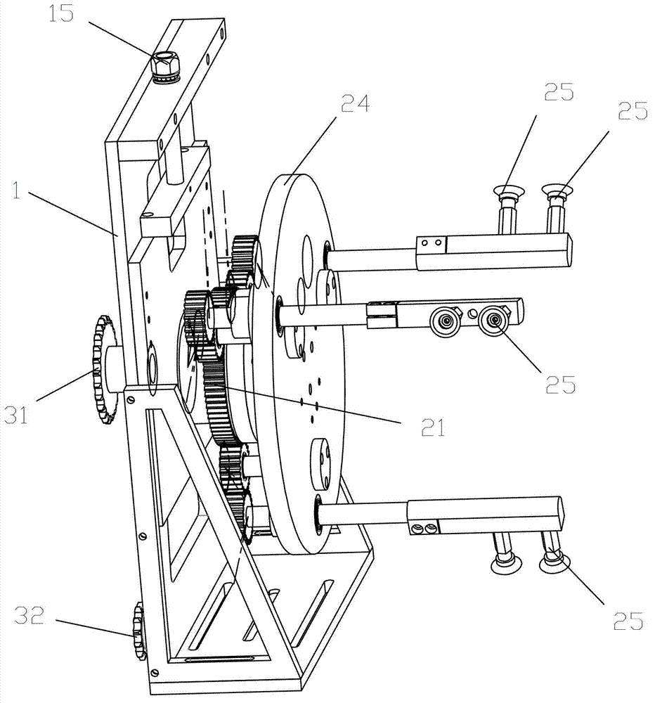
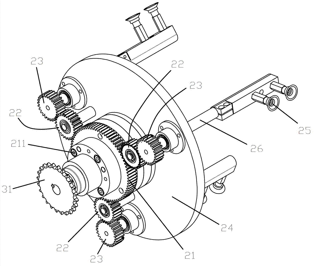
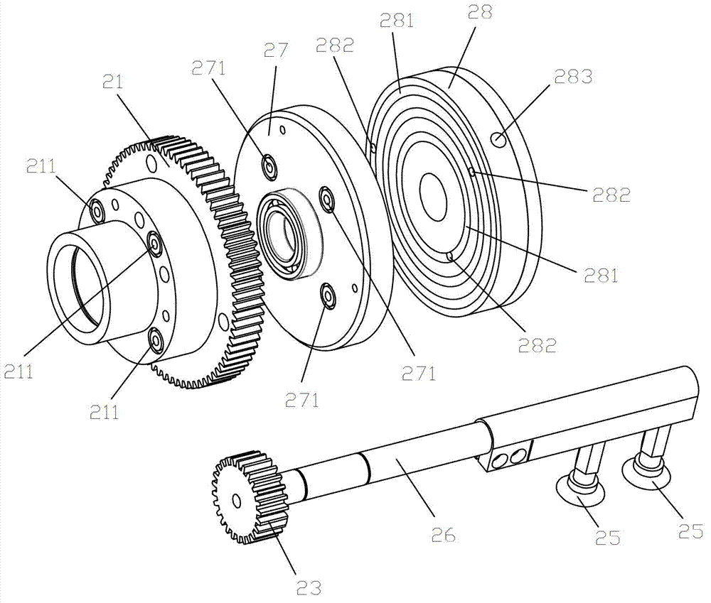
[0029] refer to Figure 1-7 : Pneumatic control automatic box unloading device, comprising a support 1, a power input mechanism, a rotation and displacement mechanism, the rotation and displacement mechanism includes a fixed wheel 21 fixedly installed on the support 1, an intermediate wheel 22 engaged with the fixed wheel 21 , the self-rotating wheel 23 meshed with the intermediate wheel 22, the fixed wheel 21 rear is provided with a rotating large disk 24, the output shaft of the power input mechanism passes through the fixed wheel 21 and is connected with the rotating large disk 24 keys, and the self-rotating wheel 23 The wheel shaft passes through the rotating large disk 24 and is provided with two suction cups 25 on the self-rotating wheel 23 axle at the back of the rotating large disk 24. The gas passage 26 communicated with the suction cup 25 is arranged in the descri...


PUM


Abstract

The invention relates to a pneumatic automatic box laying-down device which comprises a support, a power input mechanism and a rotating shifting mechanism. The rotating shifting mechanism comprises a fixed wheel fixedly arranged on the support, an idle gear meshed with the fixed wheel and a free wheel meshed with the idle gear. A rotating large disc is arranged on the rear side of the fixed wheel, an output shaft of the power input mechanism penetrates through the fixed wheel to be fixedly connected with the rotating large disc, a free wheel axle penetrates through the rotating large disc, a sucker is arranged on the free wheel axle on the back of the rotating large disc, an air channel communicated with the sucker is arranged in the free wheel and the free wheel axle, the air channel is connected with an air pump, and an electromagnetic valve controlling air sucking and inlet air is arranged on a connecting pipeline of the air pump and the air channel. The pneumatic automatic box laying-down device can achieve sucking and laying-down of material boxes at any position and is low in cost.

Description

technical field [0001] The invention relates to an automatic box unloading device. Background technique [0002] With the deepening of the aging population in the country, the pharmaceutical market is further expanding, and the demand for medicines is gradually increasing. However, the traditional manual carton packaging of medicines has low work efficiency, and manual handling of cartons is required. Manual operation makes the entire industry develop Footsteps are affected. Therefore, the automatic lower box device that can automatically suck and put down the box body arises at the historic moment. [0003] Existing automatic box unloading device, such as the patent number is 201120183356.5, the date of authorization announcement is December 21, 2011, and the name is a Chinese utility model patent for a crystal swing box machine unloading device. Shaped frame, material box and material box placement plate are installed and composed. The material box is placed in the U-sha...

Claims


Application Information

Patent Timeline
Patent Type & Authority Applications(China)
IPC IPC(8): B65G47/91
Inventor 许震宇徐林燕宁晓斌夏航
Owner ZHEJIANG UNIV OF TECH
Why Eureka
Try Eureka