Sample warper

A warping machine and fancy technology, applied in warping machines, textiles, papermaking, tool manufacturing, etc., can solve the problems of warp yarn cutting and unwinding difficulty, increasing difficulty, warping speed limitation, etc.

Active Publication Date: 2014-12-24
KARL MAYER STOLL R&D GMBH
View PDF7 Cites 0 Cited by
  • Summary
  • Abstract
  • Description
  • Claims
  • Application Information

AI Technical Summary

Problems solved by technology

[0007] However, as warping speeds increase, it becomes more and more difficult to ensure that the threads enter said ideal position relative to the warp bars
If the thread is incorrectly aligned under the warp bar, although it should be aligned above the warp bar or vice versa, it is relatively difficult to sequentially cut and unwind the warp yarns
Therefore, there is a certain limitation on the warping speed

Method used


Image

  • Sample warper
  • Sample warper

Examples


Embodiment Construction

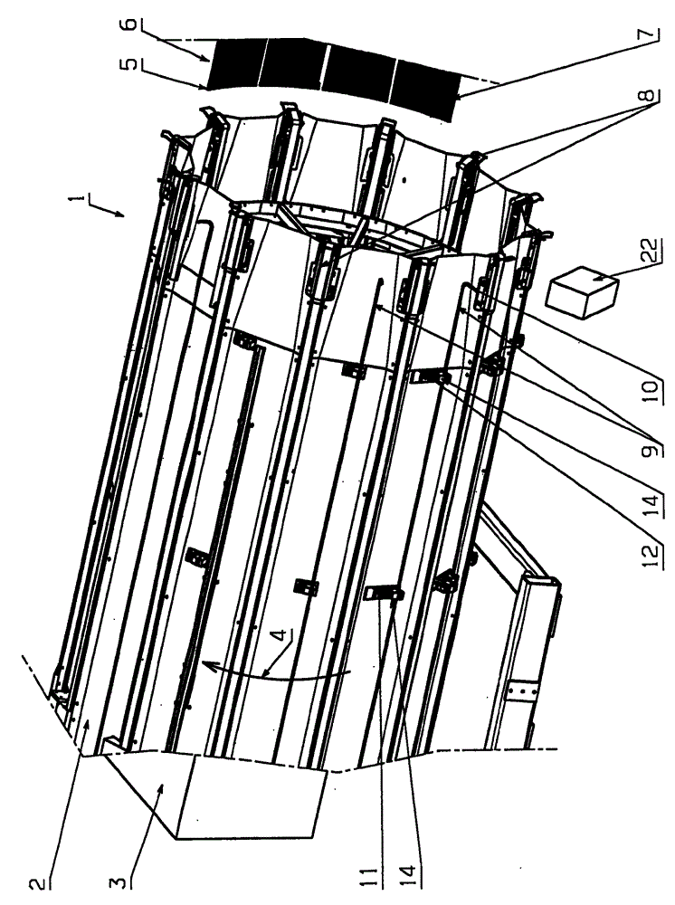
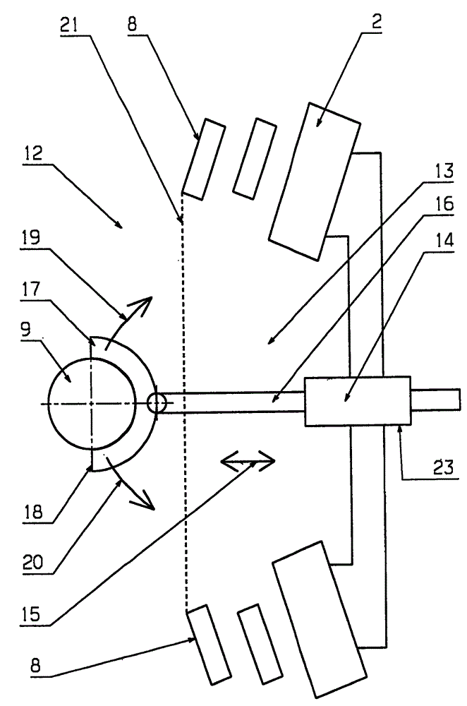
[0023] figure 1 A pattern warping machine 1 is shown schematically with a warping cylinder 2 connected to a rotary drive 3 which is only schematically shown. During winding, the rotary drive 3 is able to turn the warping cylinder 2 in the direction indicated by the arrow 4 .

[0024] A plurality of bobbins are mounted on creels, not shown in detail. In this exemplary embodiment, up to 128 bobbins can be mounted on the creel. The thread is drawn from each bobbin and guided through the thread guide eyelet 5 of the thread guide 6 . All yarn guides 6 together form a yarn guide device 7 .

[0025] During warping, that is to say during the production of warp effects, the thread guide 6 is at rest in the direction of rotation 4 of the warping cylinder 2 . However, the thread guide 6 can be moved in the axial direction, that is to say parallel to the axis of the warping cylinder 2 , to be precise, the thread guide eyelets 5 are guided in the axial direction on the warping cylinder...


PUM


Abstract

#CMT# # / CMT# The sample chain wrapping machine (1) has a warping drum (2), a thread guide assembly (7) with a thread guide (6), and multiple sub bars (9). The thread guide and the warping drum are movable relative to each other in a rotation direction around the axis of the warping drum. The sub bars are positioned in different radial positions relative to the axis of the warping drum. The sub bars distributed over their length are detachably connected with two positioning drives (14) and are displaceable by the positioning drives. A sensor arrangement (22) is connected with the positioning drives. #CMT#USE : # / CMT# Sample chain wrapping machine, particularly short chain wrapping machine for producing a sample chain. #CMT#ADVANTAGE : # / CMT# The thread guide and the warping drum are movable relative to each other in a rotation direction around the axis of the warping drum, where the sub bars distributed over their length are detachably connected with two positioning drives and are displaceable by the positioning drives, and hence ensures an improved sample chain wrapping machine that allows high speed warping and also ensures that the sub bars are easily removed from the positioning, if required during the unwinding of the finished chain. #CMT#DESCRIPTION OF DRAWINGS : # / CMT# The drawing shows a perspective view of a sample chain wrapping machine. 1 : Sample chain wrapping machine 2 : Warping drum 6 : Thread guide 7 : Thread guide assembly 9 : Sub bars 14 : Positioning drives 22 : Sensor arrangement.

Description

technical field [0001] The invention relates to a fancy warping machine with a warping cylinder, a yarn guide device and a plurality of warping rods, the yarn guide device having at least one yarn guide, wherein the yarn guide and the warping cylinder can be wound The axes of the warp cylinders move relative to each other in the direction of rotation and provide means for guiding the thread, for each warp parting rod the thread is guided by a thread guide above or below said warp parting rod. Background technique [0002] Effect warping machines, also called "short warping machines", are used to produce warp threads of limited length during which it is desirable to preserve as many pattern types as possible. [0003] For this purpose, so-called tows are wound onto the circumference of the warping cylinder. A tow of this type may comprise one or more filaments arranged adjacent to each other. After the warp yarn of required length has been wound, the tow is deflected in suc...

Claims


Application Information

Patent Timeline
Patent Type & Authority Patents(China)
IPC IPC(8): D02H3/00D02H13/00
CPCD02H9/00D02H3/04
Inventor J.霍姆M.富尔A.鲍曼
Owner KARL MAYER STOLL R&D GMBH
Why Eureka
Try Eureka