Textile technology device having an automatically flashing display

A technology, indicating technology, applied in the field of devices used in textile technology, can solve problems such as not being discovered, and achieve the effect of simple realizability

Active Publication Date: 2013-01-02
MEMMINGER IRO GMBH
View PDF7 Cites 0 Cited by
  • Summary
  • Abstract
  • Description
  • Claims
  • Application Information

AI Technical Summary

Problems solved by technology

Therefore, an undesired state (such as a broken yarn) might go undetected for a long period of time, which is of course unacceptable

Method used


Image

  • Textile technology device having an automatically flashing display
  • Textile technology device having an automatically flashing display
  • Textile technology device having an automatically flashing display

Examples


Embodiment Construction

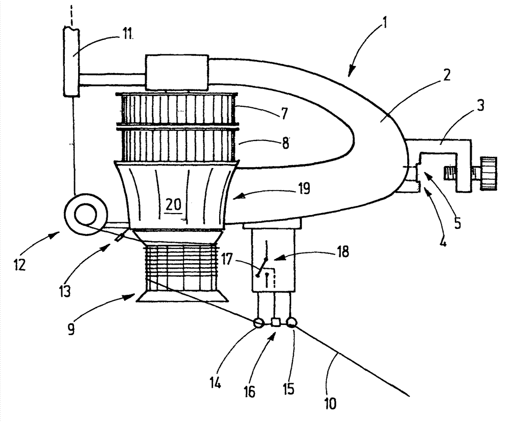
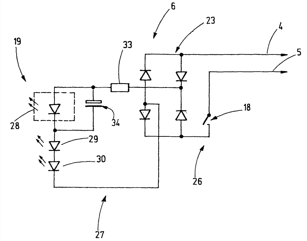
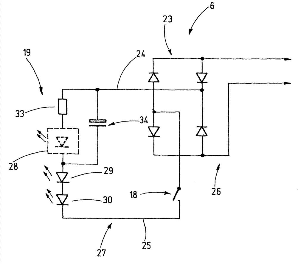
[0023] In FIG. 1 a yarn delivery device 1 is shown as an example of a device used in textile technology. The yarn delivery device 1 comprises a support 2 which is provided with a coupling 3 for fastening the yarn delivery device 1 to, for example, a machine ring of a knitting machine. In the area of ​​the connector 3 there are usually also plug-in electrical contacts 4 , 5 which are used for contacting cables arranged, for example, on the machine ring of the knitting machine. A signaling device 6 , which will be described later (shown for example in FIG. 2 ), is supplied with voltage via plug-in electrical contacts 4 , 5 . In addition, at least in a preferred embodiment, a faulty state (such as a broken yarn) is signaled to the center of the knitting machine via the plug-in electrical contacts 4, 5 and thus the contacted cables. controller.

[0024] The yarn delivery device 1 has a vertically oriented shaft (welle), not specifically shown in FIG. 1 , which is mounted rotatab...


PUM


Abstract

A textile technology device having a signaling device (6) has a flashing circuit for displaying a defined operating state, such as a thread breakage. Said circuit comprises of a flashing LED (28), to which at least one regular LED (29) is series connected. The circuit arrangement is cost-effective and sturdy. It allows both optical signaling of an error state and an electrical signaling of the error state to a central control unit, which can analyze the power requirement of the signaling unit for detecting the error state. The central control unit can further distinguish between simple line short circuits, or other electrical error states, from a properly reported error, because the flashing circuit comprising the flashing LED (28) and at least one further regular LED (29) records a chronologically periodically changing amount of power, once the circuit responds.

Description

[0001] This application is a PCT patent application submitted on October 24, 2007 that has entered the Chinese national phase (Chinese national application number is 200780048085.9, international application number is PCT / EP2007 / 009202, the title of the invention is "textile with automatic flashing indicator Apparatus used in the technology") divisional application. technical field [0002] The invention relates to a device for textile technology with a signaling device for signaling a specific operating state. Background technique [0003] Devices used in textile technology, such as yarn delivery devices of knitting machines, yarn sensors, yarn monitors, etc., are often arranged in knitting machines and must be monitored by the knitter. In this regard, it is known from document DE-AS 24 58 884 to arrange a yarn monitor on such a device used in textile technology, which yarn monitor comprises an electric switch. The indicator light is controlled via an electric switch and f...

Claims


Application Information

Patent Timeline
Patent Type & Authority Applications(China)
IPC IPC(8): D04B35/14
CPCD04B35/14
Inventor V.鲍勒P.罗思富斯
Owner MEMMINGER IRO GMBH
Why Eureka
Try Eureka