Supercharge Your Innovation With Domain-Expert AI Agents!

Transmission shaft sealing device of grate coolers

A technology of sealing device and transmission shaft, which is applied in the direction of engine sealing, mechanical equipment, engine components, etc., which can solve the problems of reduced work efficiency, time-consuming and troublesome, difficult pressure balance adjustment of seal 56, etc., and achieves convenient lubricating oil and easy disassembly Easy and convenient pressure adjustment effect

Active Publication Date: 2015-06-17
XINGHUA DONGFANG MACHINERY
View PDF7 Cites 0 Cited by
  • Summary
  • Abstract
  • Description
  • Claims
  • Application Information

AI Technical Summary

Problems solved by technology

To carry out these tasks, at first the connecting rod must be dismantled to remove the sealing device 50 that is sleeved on the transmission shaft, so as to replace parts or add lubricating oil, which is time-consuming and troublesome, and the work efficiency is greatly reduced.
In addition, there should be no gap between the sealing member 56 and the inner surface of the sealing cover 59, which requires the spring to exert an appropriate and balanced force on the sealing member 56, but the pressing of the sealing member 56 in the above-mentioned sealing device depends on the compression of multi-point distribution. The spring realizes that it is very difficult to adjust the pressure balance of each point on the seal 56

Method used


Image

  • Transmission shaft sealing device of grate coolers
  • Transmission shaft sealing device of grate coolers
  • Transmission shaft sealing device of grate coolers

Examples


Embodiment Construction

[0049] The present invention will be further described below in conjunction with the accompanying drawings and embodiments.

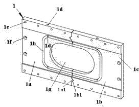
[0050] control figure 1 The sealing plate 1 is a rectangular plate and is formed by splicing the first half sealing plate 1a and the second half sealing plate 1b. The chute 1c provided on one side of the sealing plate 1 is set at the center of the bottom surface of the chute. A waist-shaped hole 1g, a rectangular annular oil groove 1h is also provided on the bottom surface of the chute around the periphery of the waist-shaped hole 1g; and the above-mentioned waist-shaped hole 1g and oil groove 1h are respectively arranged in the first half of the sealing plate 1a in two completely symmetrical parts and on the second half-sealed plate 1b. At least one triangular protrusion 1a1 and a triangular groove 1b1 are provided on the splicing surface 1i of the two halves of the sealing plate; preferably as figure 1 As shown, a triangular protrusion 1a1 and a t...


PUM


Abstract

The invention relates to a transmission shaft sealing device of a grate cooler. The transmission shaft sealing device of the grate cooler is mounted on the grate cooler and a transmission shaft and comprises an elastic pressing plate, a half clamping ring, a half pressing plate ring, a sliding plate and a sealing plate. The sliding plate and the sealing plate are formed by jointing; a waist-shaped hole, a sliding groove, an annular oil groove and an oil hole are arranged on the sealing plate; a circular hole is arranged on the sliding plate; two half clamping rings are symmetrically jointed to form a circular ring-shaped clamping ring fixed on the transmission shaft; the sliding plate is inserted in the sliding groove of the sealing plate; the sealing plate is fixed on the side plate of the grate cooler; the hole on the sliding plate and the waist-shaped hole on the sealing plate are sleeved on the transmission shaft; two half pressing plate rings are symmetrically jointed to form a circular ring-shaped pressing plate ring sleeved on the transmission shaft between the clamping ring and the sliding plate; the elastic pressing plate is connected on the pressing plate ring; the lower end of the elastic pressing plate presses and touches on the sliding plate; and the pressing plate leans against the lamping ring. The transmission shaft sealing device of the grate cooler has the advantages that the sealing device is easy to dismount, convenient to exchange or maintain quick-wear parts in the sealing device, featured with good lubrication effect on a frication surface and capable of mounting and positioning fast and accurately.

Description

technical field [0001] The invention relates to a grate cooler, in particular to a sealing device for a transmission shaft of a grate cooler. Background technique [0002] The grate bed in the grate cooler performs reciprocating motion, which is realized by the rotating power shaft 101 driving the transmission shaft 103 through the connecting rod 102, please refer to Figure 9 , Figure 10 . The grate bed is connected to the drive shaft 101 of the grate bed, the two ends of the power shaft 101 are respectively connected to the flange 105 , one end of the connecting rod 102 is eccentrically and rotatably connected to the flange 105 , and the other end is connected to the drive shaft 103 . Both ends of the transmission shaft 103 are respectively connected with a slidable sealing member 56, and the sealing member slides in a corresponding slide groove. In this way, a crank linkage is formed between the connecting rod 102, the sealing member 56, the power shaft 101, and the po...

Claims


Application Information

Patent Timeline
Patent Type & Authority Patents(China)
IPC IPC(8): F16J15/16F16J15/18F16J15/56C04B7/47
Inventor 王祥潘丰强
Owner XINGHUA DONGFANG MACHINERY
Features
  • R&D
  • Intellectual Property
  • Life Sciences
  • Materials
  • Tech Scout
  • Unparalleled Data Quality
  • Higher Quality Content
  • 60% Fewer Hallucinations
Learn More