Rotary outflow control device and application method thereof

A technology of flow control and rotation, which is applied in the direction of valve devices, watering devices, botanical equipment and methods, etc., can solve the problems of uneven water distribution flow in branch pipes, small water output in branch pipes, and large water output in branch pipes, etc., so as to improve the comprehensive Utilization and efficiency, mitigation of shortages, effects of improving balance

Inactive Publication Date: 2013-01-02
CHINA AGRI UNIV
View PDF6 Cites 12 Cited by
  • Summary
  • Abstract
  • Description
  • Claims
  • Application Information

AI Technical Summary

Problems solved by technology

At present, many farmland irrigation, especially large-scale farmland irrigation, rely on long pipelines for water delivery. The branch pipes near the main pipe entrance have a large water output, and the branch pipes far away from the main pipe entrance have a small water output, resulting in uneven water distribution of different branch pipes.
In order to meet the irrigation volume of the irrigation area far away from the main pipe inlet, the irrigation water volume of the irrigation area near the main pipe inlet will exceed the demand, resulting in waste of water resources and increasing the labor cost of irrigation and replacement of water volume adjustment equipment
There are many kinds of water volume adjustment equipment in farmland irrigation, but the existing water volume adjustment equipment generally cannot adjust the irrigation pressure and irrigation quota, nor can it automatically adjust the flow rate.
[0003] In the Chinese patent application number 200810112192.X, authorized announcement number CN101278640B, titled "an irrigation device and irrigation method thereof", a control device suitable for alternate irrigation of root system partitions is disclosed, and the unit length pipes are quickly connected by clamps. Each part of the emitter can be quickly disassembled and assembled, but it does not solve the problem of adjusting the uniformity of the water outlet after connecting multiple outlet pipe units

Method used


Image

  • Rotary outflow control device and application method thereof
  • Rotary outflow control device and application method thereof
  • Rotary outflow control device and application method thereof

Examples


Embodiment Construction

[0053] The present invention will be described in detail below in conjunction with the accompanying drawings and embodiments.

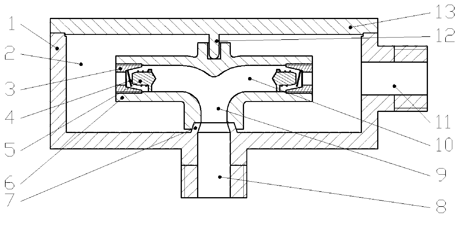
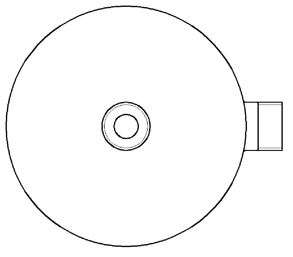
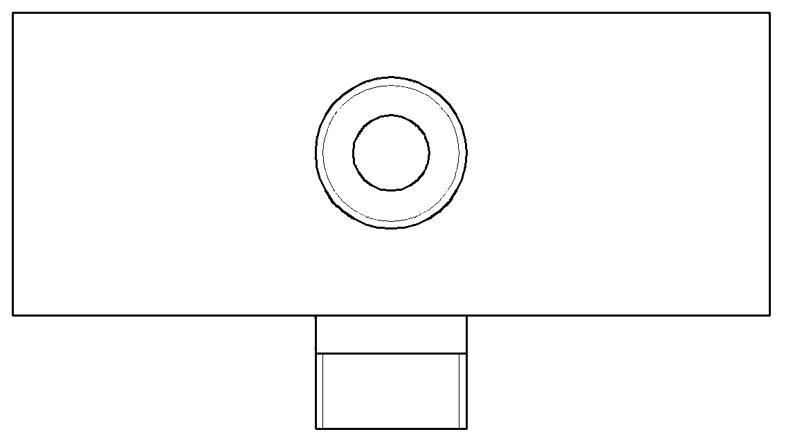
[0054] Such as Figure 1 ~ Figure 3 Shown are the structural front view, bottom view and side view of the rotary outflow control device of the present invention. The rotary outflow control device includes a housing 1, a side cover 13, a rotating member 6 and two sets of piston assemblies.

[0055] Wherein, the housing 1 is made of plastic material, and one side of the cylindrical top surface is provided with an axial water inlet 8 for connecting the water inlet pipe, and the water inlet 8 extends a conical hub boss 7 toward the inner cavity 2 of the housing; One side of the cylindrical surface of body 1 is provided with a radial water outlet 11; the outer sides of the water inlet 8 and the water outlet 11 are respectively provided with connecting threads for connecting with the water inlet pipe and the water outlet pipe respectively.

[0056] A rota...


PUM


Abstract

The invention relates to farmland irrigation equipment, and particularly relates to a rotary outflow control device comprising a rotating component and capable of automatically adjusting an outlet flow, and an application method thereof. The rotary outflow control device comprises a shell (1); a lateral cover (13) is arranged on the shell (1); a rotating piece (6) is mounted inside a shell inner cavity (2); a water inlet runner (9) and two water outlet runners (10) are arranged inside the rotating piece (6); the water inlet runner (9) is communicated with a water inlet (8); and two groups of piston assemblies are respectively mounted at the tail ends of the two water outlet runners (10). With the adoption of the rotary outflow control device provided by the invention, the amounts of water flowing through the water inlet and the water outlet can be automatically adjusted within an adjustable range, so that the balance of the water outlet flow can be improved. The rotary outflow control device has the advantages of simple structure and easiness of dismounting, and can be widely applied in agriculture irrigation production.

Description

technical field [0001] The invention relates to a farmland irrigation equipment, in particular to a rotary outflow control device including a rotating component for automatic regulation of outlet flow and a method for using the same. Background technique [0002] Surface irrigation is still an irrigation technology widely used in the world, especially in developing countries. More than 98% of the irrigated area in my country still uses traditional surface irrigation technology, which has great potential for water saving. Low-pressure pipeline water delivery is currently the most commonly used field irrigation technology. Water distribution form. At present, many farmland irrigation, especially large-scale farmland irrigation, rely on long pipelines for water delivery. The branch pipes close to the main pipe entrance have a large water output, and the branch pipes far away from the main pipe entrance have a small water output, resulting in uneven water distribution of differen...

Claims


Application Information

Patent Timeline
Patent Type & Authority Applications(China)
IPC IPC(8): F16K17/34A01G25/16
Inventor 唐学林安阳杜太生
Owner CHINA AGRI UNIV
Why Eureka
Try Eureka