AI technical title is built by Patsnap AI team. It summarizes the technical point description of the patent document.
A storage tank, gas technology, applied in the direction of combustible gas purification, combustible gas purification/reconstruction, fixed capacity gas storage tank, etc.
Active Publication Date: 2013-01-02
LIUZHOU JINGYANG ENERGY SAVING TECH RES DEV
View PDF6 Cites 3 Cited by
Summary
Abstract
Description
Claims
Application Information
AI Technical Summary
This helps you quickly interpret patents by identifying the three key elements:
Problems solved by technology
Method used
Benefits of technology
Problems solved by technology
[0002] At present, in the production and operation of special gases for welding and cutting, welding and cutting operations, household life and catering processing, most of the gases used have many impurities, low purity and low moisture content. Large, low thermal efficiency, poor use effect and low energy saving and environmental protection rate, and the gas storage tank used is also designed to lag behind, bulky, single function, not widely practical, inconvenient to carry, high production cost, poor energy saving and environmental protection, low safety factor and other disadvantages
Method used
Image
Click on the blue label to locate the original text in one second.
Reading with bidirectional positioning of images and text.
Examples
example
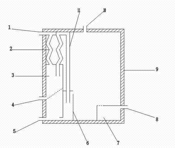
[0018] Connect the gas inlet valve 1 and the pure gas valve 10 of the gas purifying condensate storage tank to the external gas supply and gas pipe valve respectively, and inject condensate or inert agent from the coagulant valve 8, then open the gas inlet valve 1 and the gas enters the quake The first group of bent pipes before the filter tube 2 is subjected to primary double purification and enters the separation tank 3. The gas is filtered and separated from the waste residue and water through the nano-micro filter in the separation tank 3, and then enters the curved filter tube 2. The rear group of bent pipes is subjected to secondary purification. The compound purification enters the purification pipe 11 and the purification tank 6 in turn. After the gas further precipitates impurities and moisture in the purification tank 6, the precipitated impurities and moisture enter the lower side of the separation tank through a check valve on one side to be discharged, while the pur...
PUM
Abstract
The invention provides a purifying, condensing and storing tank for gas. The tank comprises outer arrangement and inner arrangement. The outer arrangement and the inner arrangement are composed of an inlet valve, a slag removal valve, a drain valve, a coagulant valve, a pure gas valve, a bent filter tube, a separation tank, a purification tank, a coagulant tank, a gas storage tank, and a purification tube, wherein the inlet valve is arranged at one side of the upper end of the gas storage tank, the slag removal valve is arranged at one side of the lower end of the gas storage tank, the drain valve is installed at one side of the lower end of the gas storage tank, the coagulant valve is mounted at one side of the lower end of the gas storage tank, the pure gas valve is arranged at an upper side of the gas storage tank, the bent filter tube is mounted at the inner side of the upper end of the gas storage tank and comprises two sets of identical bent pipes, the separation tank is arranged at the inner side of the gas storage tank, the central part of the separation tank is provided with a microfiltration mesh, the purification tank is arranged at one side of the separation tank, a back-pressure valve at the lower side of the purification tank is communicated with the separation tank, the coagulant tank is arranged at the lower side in the gas storage tank and is communicated with the coagulant valve, the gas storage tank is arranged at the outer sides of the separation tank and the coagulant tank, and the purification tube is arranged at one side of the separation tank and is communicated with the bent filter tube. The purifying, condensing and storing tank for gas provided by the invention has the advantages of an exquisite design structure, advanced technical characteristics, multiple functions, practicality, convenience, slag removal and purification of draining, high-quality purification, condensation and storage of gas, high efficiency, energy saving and environmental protection.
Description
technical field [0001] The invention relates to a storage tank, in particular to a fuel gas purification and condensation storage tank. Background technique [0002] At present, in the production and operation of special gases for welding and cutting, welding and cutting operations, household life and catering processing, most of the gases used have many impurities, low purity, high moisture content, low thermal efficiency, poor use effect and low energy saving and environmental protection rate, while The gas storage tanks used also have disadvantages such as backward design, bulky constitution, single function, limited practicality, inconvenient transportation, high production cost, poor energy saving and environmental protection, and low safety factor. For this reason, it is necessary to invent a gas purification purification condensate storage tank which is more advanced in technology and can comprehensively solve the problems of used gas and storage tank technology and i...
Claims
Application Information
Patent Timeline
Application Date:The date an application was filed.
Publication Date:The date a patent or application was officially published.
First Publication Date:The earliest publication date of a patent with the same application number.
Issue Date:Publication date of the patent grant document.
PCT Entry Date:The Entry date of PCT National Phase.
Estimated Expiry Date:The statutory expiry date of a patent right according to the Patent Law, and it is the longest term of protection that the patent right can achieve without the termination of the patent right due to other reasons(Term extension factor has been taken into account ).
Invalid Date:Actual expiry date is based on effective date or publication date of legal transaction data of invalid patent.

