
Method for simulating and calculating dynamic stress of a vehicle body structure of high-speed tracked vehicle

A technology of dynamic stress and car body structure, applied in calculation, special data processing applications, instruments, etc., can solve problems such as coupling, difficulty in accurately obtaining the boundary load conditions of car body structure, and inability to meet design requirements

Inactive Publication Date: 2013-01-02
ACADEMY OF ARMORED FORCES ENG PLA
View PDF3 Cites 23 Cited by
  • Summary
  • Abstract
  • Description
  • Claims
  • Application Information

AI Technical Summary

Problems solved by technology

However, there are two main problems in the calculation of body stress of high-speed tracked vehicles based on the finite element method: one is that the boundary load borne by the car body structure is difficult to obtain
Due to the complexity of the connection of the car body structure, it is difficult to accurately obtain all the boundary load conditions of the car body structure through the means of testing, especially in the design stage, because there is no test sample car, only the boundary load of the same type of vehicle can be used, so The obtained analysis and calculation results obviously cannot meet the actual design requirements
The second is the coupling problem between the dynamic characteristics of the vehicle system and the structural characteristics of the vehicle body
However, so far, in the field of research on the structural strength of high-speed tracked vehicles, there are still no relevant literature records on the consideration of the interaction between vehicle system dynamics and structural dynamic characteristics and the calculation of structural dynamic stress.

Method used


Image

  • Method for simulating and calculating dynamic stress of a vehicle body structure of high-speed tracked vehicle
  • Method for simulating and calculating dynamic stress of a vehicle body structure of high-speed tracked vehicle
  • Method for simulating and calculating dynamic stress of a vehicle body structure of high-speed tracked vehicle

Examples


Embodiment Construction

[0029] The present invention will be described in detail below in conjunction with the accompanying drawings.

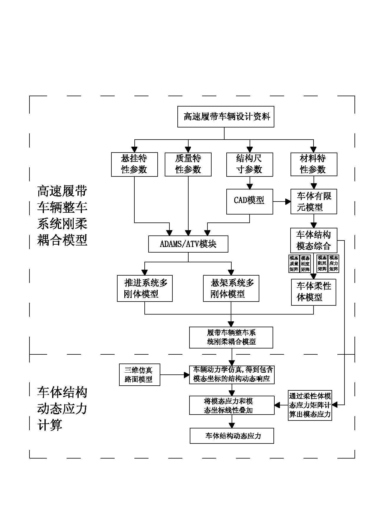
[0030] Such as figure 1 As shown, a high-speed tracked vehicle body structure dynamic stress simulation calculation method of the present invention includes building a high-speed tracked vehicle vehicle system rigid-flexible coupling model based on the modal synthesis method and a vehicle body structure based on the modal stress recovery method There are two implementation steps of dynamic stress calculation. in,

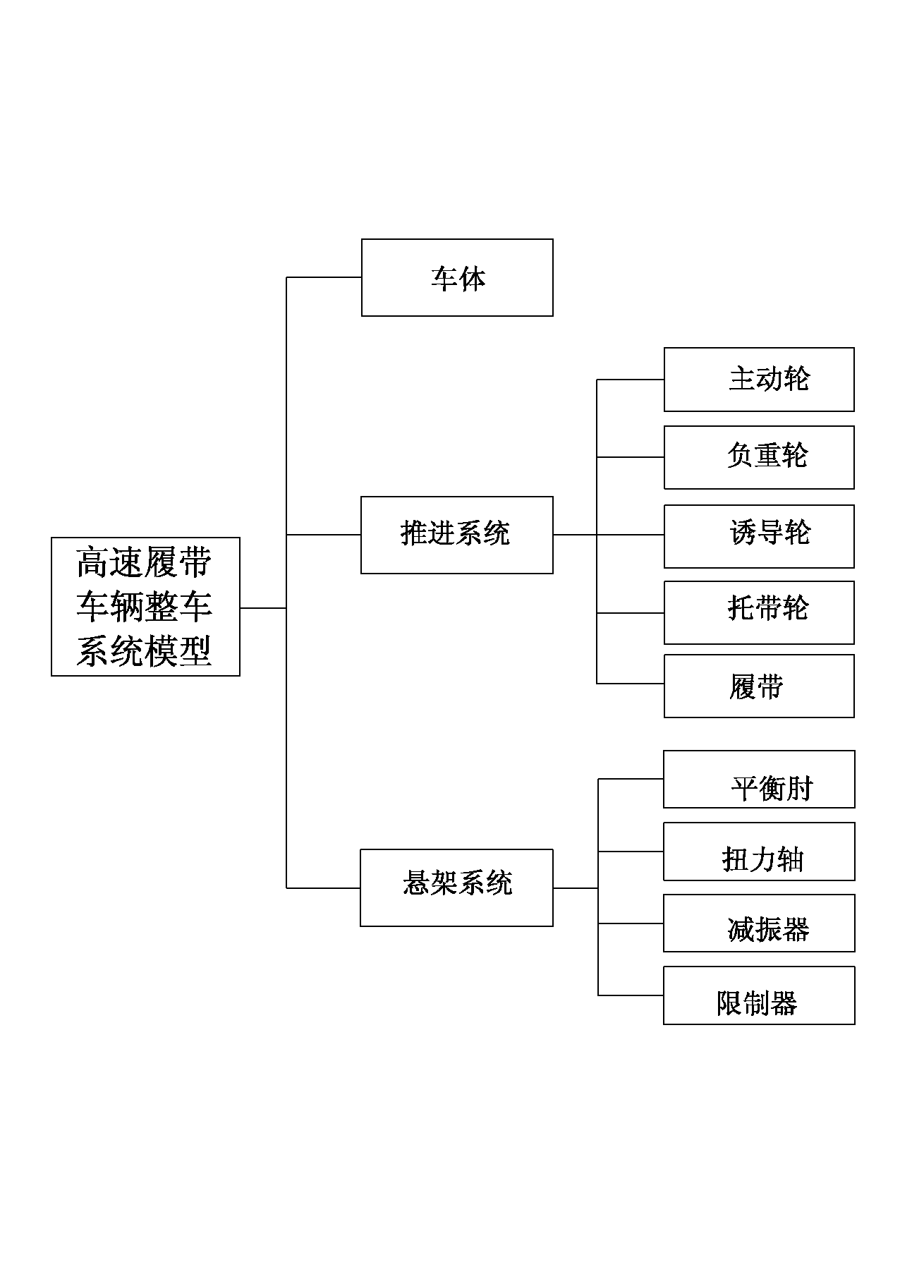
[0031] Step 1: Construct a rigid-flexible coupling model of the high-speed tracked vehicle system based on the modal synthesis method. The rigid-flexible coupling model of the high-speed tracked vehicle system includes the multi-rigid body model of the propulsion system, the multi-rigid body model of the suspension system and the flexible body model of the vehicle body. In the computer, use ADAMS software to construct the multi-rigid body model of the p...


PUM


Abstract

The invention relates to the technical field of calculation, simulation and estimation of dynamic stress of a bearing structure of a high-speed tracked vehicle, in particular to a method for simulating and calculating dynamic stress of a vehicle body structure of the high-speed tracked vehicle. The method comprises two implementation steps of constructing a finished high-speed tracked vehicle system rigid-flexible coupling model based on a modal comprehensive method and calculating the dynamic stress of the vehicle body structure based on a modal stress recovering method. An integrated rigid body suspension system model, a propelling system model and a high-speed tracked vehicle rigid-flexible coupling complex dynamics model with a vehicle body structure finite element model are built by adopting a modal comprehensive technology, and the characteristics of the coupling dynamics between the vehicle system dynamics and the structure dynamics are accurately reflected. The method can obtain structural edge load at a designing and development stage of the high-speed tracked vehicle and simultaneously obtain structure dynamic stress, and provides effective means for design and improvement of a system structure of the high-speed tracked vehicle.

Description

technical field [0001] The invention relates to the technical field of dynamic stress calculation and simulation evaluation of a high-speed crawler vehicle bearing structure, in particular to a dynamic stress simulation calculation method for a car body structure of a high-speed crawler vehicle. Background technique [0002] When a high-speed tracked vehicle is running on a complex off-road road, the severe impact and vibration of the harsh road environment are the main reasons for the structural vibration of the high-speed tracked vehicle system, resulting in excessive structural dynamic stress or even structural damage. However, for a long time, due to the limitations of calculation methods and means, the structural design of the car body still relies on the traditional empirical design method. [0003] Since the 1990s, the finite element method has been gradually applied in the stress calculation of the body structure of high-speed tracked vehicles. However, there are tw...

Claims


Application Information

Patent Timeline
IPC IPC(8): G06F17/50
Inventor 王红岩芮强王钦龙薛劲橹
Owner ACADEMY OF ARMORED FORCES ENG PLA
Learn More