Light mixing distance experimental device

A technology of light mixing distance and experimental device, applied in the field of backlight, can solve the problems of cumbersome testing procedures and low efficiency, and achieve the effect of facilitating testing and accumulating test data.

Inactive Publication Date: 2013-01-02
BOE TECH GRP CO LTD +1
View PDF9 Cites 6 Cited by
  • Summary
  • Abstract
  • Description
  • Claims
  • Application Information

AI Technical Summary

Problems solved by technology

Usually, different film materials are installed on different backlight panels, and then powered on for testing. The testing process is cumbersome and the efficiency is low.

Method used


Image

  • Light mixing distance experimental device
  • Light mixing distance experimental device

Examples


Embodiment Construction

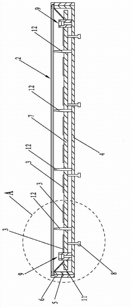
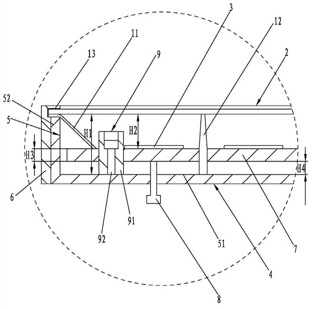
[0020] It should be noted that the light mixing distance in the direct-type backlight module refers to the distance from the bottom reflector or the light source to the film material in the direct-type backlight module, such as figure 1 and figure 2 As shown, the distance from the upper surface of the lifting pallet 7 to the film material 2 is H2, and H2 is the light mixing distance described in the present invention.

[0021] Such as figure 1 , figure 2 As shown, the light mixing distance experimental device of the embodiment of the present invention is used to experiment and determine the light mixing distance of the backlight module. The light mixing distance experimental device of the embodiment of the present invention includes:

[0022] A fixing device for fixing the film material 2 of the backlight module;

[0023] A supporting device for supporting the light source 3 of the backlight module;

[0024] The adjusting device acting on the supporting device is used to...


PUM


Abstract

The invention relates to a light mixing distance experimental device which is used for experimenting and determining the light mixing distance of a bottom lighting type backlight module. The light mixing distance experimental device comprises a fixing device, a bearing device and an adjusting device, wherein the fixing device is used for fixing a membrane of the bottom lighting type backlight module; the bearing device is used for bearing a light source of the bottom lighting type backlight module; and the adjusting device acts on the bearing device and is used for adjusting the distance between the bearing device and the membrane. The light mixing distance experimental device can be fittingly used with membranes of different manufacturers and different models, and using the light mixing distance experimental device avoids complex procedures of mounting and demounting a wrench and fixing auxiliary materials. Using the light mixing distance experimental device avoids outage during experiment, real-time adjustment and real-time luminous efficiency reflection are realized, testing and testing data accumulation are facilitated, and the variation relation between the light mixing distance and a membrane collocation scheme can be truly reflected.

Description

technical field [0001] The invention relates to the field of backlight technology, in particular to a light mixing distance experimental device for experimenting and determining the light mixing distance of a direct-type backlight module. Background technique [0002] At present, the existing LED TVs have two backlight solutions: side-type and direct-type. The obvious disadvantage of the direct-down type compared to the side-type type is that the appearance is thicker, and the comparison of the whole machine is more obvious. Direct-type LED TVs have greater advantages in picture control, and also have advantages in cost. Once there is a breakthrough in its thickness, low-cost direct-type LED TVs will fully occupy the market. The key to reducing the thickness of direct-lit LEDs is to reduce the light mixing distance, that is, to reduce the distance between the light source and the film material under the premise of ensuring the display quality. In the research and developme...

Claims


Application Information

Patent Timeline
Patent Type & Authority Applications(China)
IPC IPC(8): G09F9/33
Inventor 李鹏张晓
Owner BOE TECH GRP CO LTD
Why Eureka
Try Eureka