Vapor chamber

a technology of vapor chamber and working fluid, which is applied in the direction of cooling/ventilation/heating modification, basic electric elements, semiconductor devices, etc., can solve the problems of affecting the efficiency of heat transfer, different manufacturing process of vapor chamber and heat pipe, etc., and achieves the effect of reducing the time for vaporizing the working fluid at an earlier stage, and reducing the time of vaporization

Inactive Publication Date: 2009-12-03
GOLDEN SUN NEWS TECHN +1
View PDF19 Cites 40 Cited by
  • Summary
  • Abstract
  • Description
  • Claims
  • Application Information

AI Technical Summary

Benefits of technology

[0007]The present invention is to provide a vapor chamber, in which the wick structure on the heated end of the vapor chamber is made by means of overlapping two wick portions of different aperture diameters or densities. Furthermore, the aperture diameter of the wick portion adhered on the inner wall surface is larger that of the overlapping wick portion. Alternatively, the aperture density of the wick portion adhered on the inner wall surface is lower than that of the overlapping wick portion. Therefore, since the aperture diameter is smaller or the density is larger, the working fluid flowing therein will be dispersed more easily. The amount of dispersed working fluid is thus smaller, so that it can be vaporized faster after heated. As a result, the time for vaporizing the working fluid at an earlier stage can be reduced, thereby transmitting the heat more quickly.

Problems solved by technology

However, the manufacturing process of the vapor chamber is different from that of the heat pipe.
However, the wick structures on the heated end and the condensed end cannot make the working fluid to be vaporized quickly, which affects the efficiency of heat transfer.

Method used


Image

  • Vapor chamber
  • Vapor chamber
  • Vapor chamber

Examples


Embodiment Construction

[0015]In order to make the Examiner to better understand the characteristics and technical contents of the present invention, a detailed description relating thereto will be made with reference to the accompanying drawings. However, the drawings are illustrative only, but not used to limit the present invention.

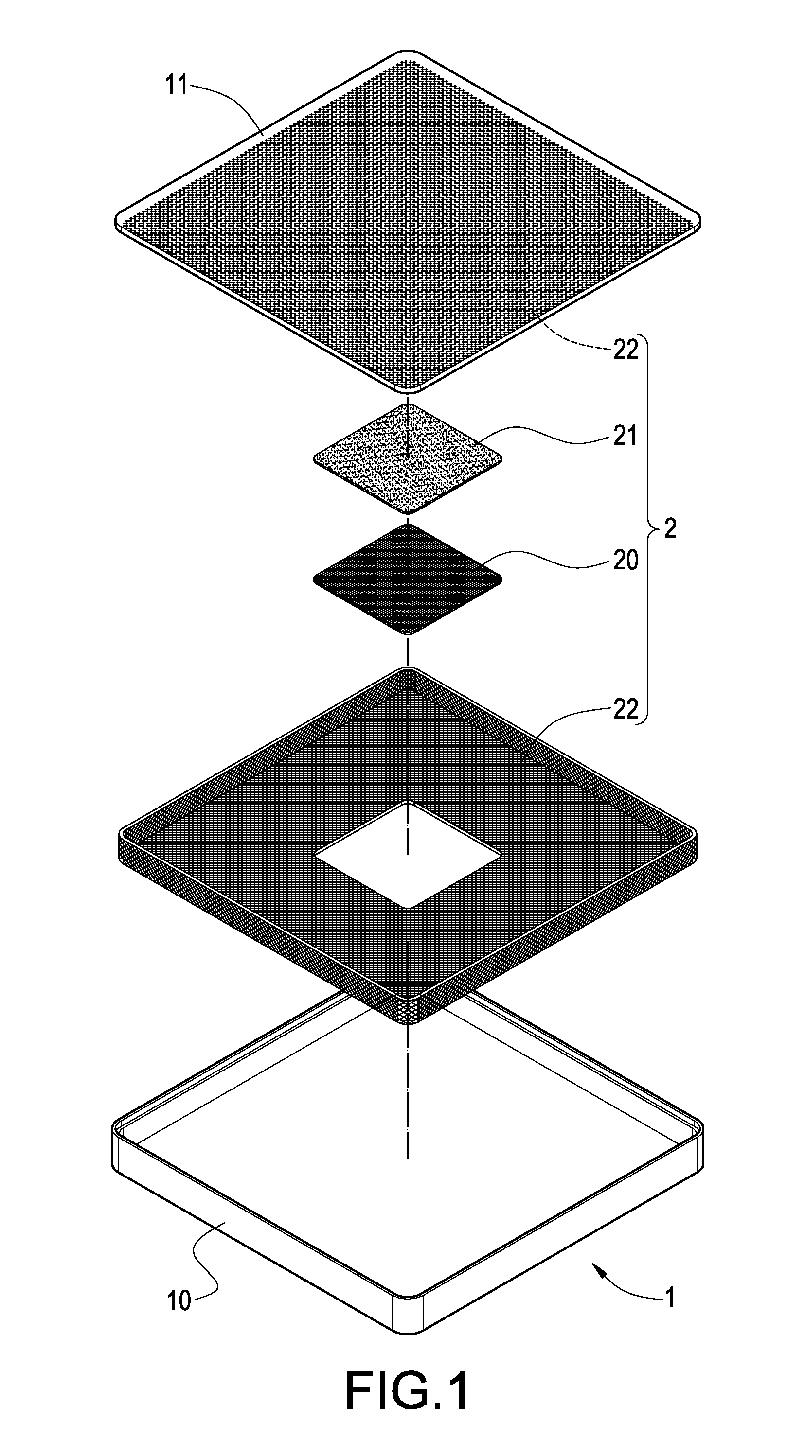
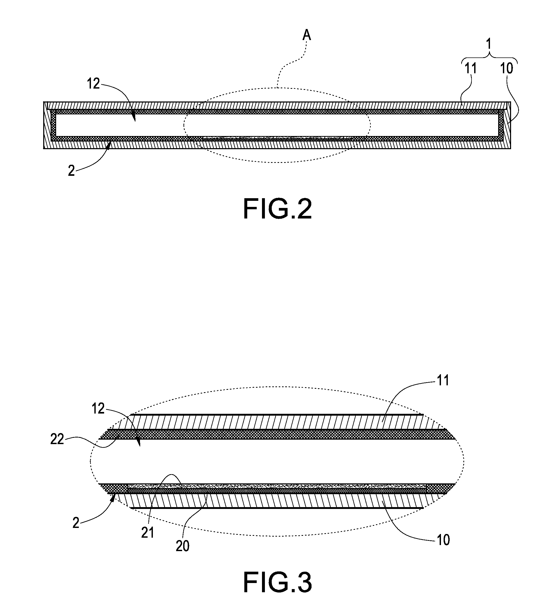
[0016]Please refer to FIGS. 1 and 2, which are an exploded perspective view and an assembled cross-sectional view of the present invention, respectively. The present invention is to provide a vapor chamber, which includes a plate 1 and a wick structure 2 adhered to each inner wall surface of the plate.

[0017]The interior of the plate 1 is hollowed and it is made of heat-dissipating materials. The plate 1 is constituted of a base 10 and a top cover 11. After the base 10 and the top cover 11 are connected with each other, the hollow space within the plate 1 forms a chamber 12. The chamber 12 is sealed and filled with a working fluid (not shown) therein. In addition, the plate 1 ...


PUM


Abstract

A vapor chamber includes a plate and a wick structure. The plate is provided therein with a working fluid, and the plate has a heated end and a condensed end. The wick structure comprises a first wick portion adhered to be opposite to the heated end, a second wick portion overlapping on the first wick portion, and a third wick portion adhered on the rest portion of a chamber. The aperture diameter of the first wick portion is larger than that of the second wick portion, or the aperture density of the first wick portion is smaller than that of the second wick portion. Therefore, the amount of working fluid attached to the second wick portion is smaller than of the first wick portion. As a result, after heated, the working fluid attached to the second wick portion will be vaporized more quickly, thereby increasing the efficiency of heat transfer and improving the heat-dissipating effect.

Description

BACKGROUND OF THE INVENTION[0001]1. Field of the Invention[0002]The present invention relates to a heat exchanger, and in particular to a vapor chamber in which a wick structure and a working fluid are provided.[0003]2. Description of Prior Art[0004]A vapor chamber is a kind of plate-like heat pipes. The principle of the vapor chamber is the same as that of the heat pipe. Via an internal vacuum environment, a working fluid filled therein can generate phase change when heated, so that the heat can be transferred by vapors. Then, the working fluid returns to its liquid state after being cooled, so that the working fluid can be circulated in the vapor chamber.[0005]However, the manufacturing process of the vapor chamber is different from that of the heat pipe. The pipe body of the heat pipe is usually formed into a tubular body. After sealing one end of the pipe body, at the open end of the heat pipe, some processes are performed, such as the filling of working fluid, degassing or vacu...

Claims


Application Information

Patent Timeline
Patent Type & Authority Applications(United States)
IPC IPC(8): F28D15/00
CPCF28D15/0233F28D15/046F28D2021/0029H01L23/427H01L2924/0002H01L2924/00
Inventor LIN, KUO-LENLIU, WEN-JUNGLIN, CHEN-HSIANGCHENG, CHIH-HUNGHUANG, JU-TSU
Owner GOLDEN SUN NEWS TECHN
Why Eureka
Try Eureka