Polymer dispersed crystal liquid film driving method and direct-current power source driving device
A technology of dispersed liquid crystal and DC power supply, applied in the direction of instruments, static indicators, etc., can solve the problems of inconvenience of use and portability, and achieve the effects of high safety, good optical performance and convenient use.
- Summary
- Abstract
- Description
- Claims
- Application Information
AI Technical Summary
Problems solved by technology
Method used
Image
Examples
Embodiment 1
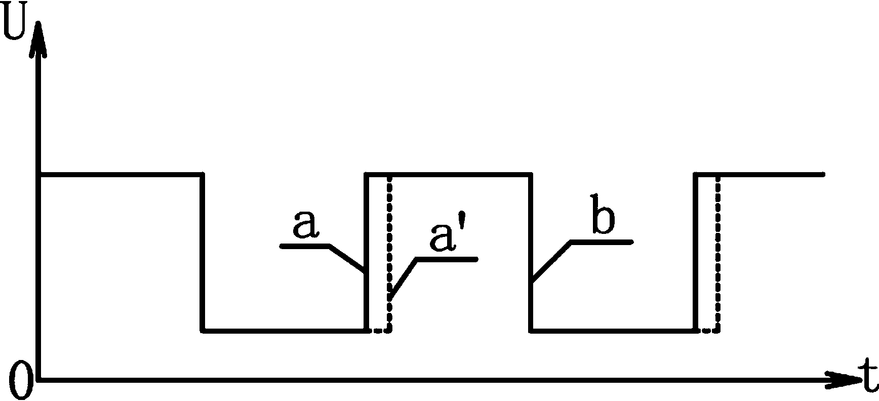
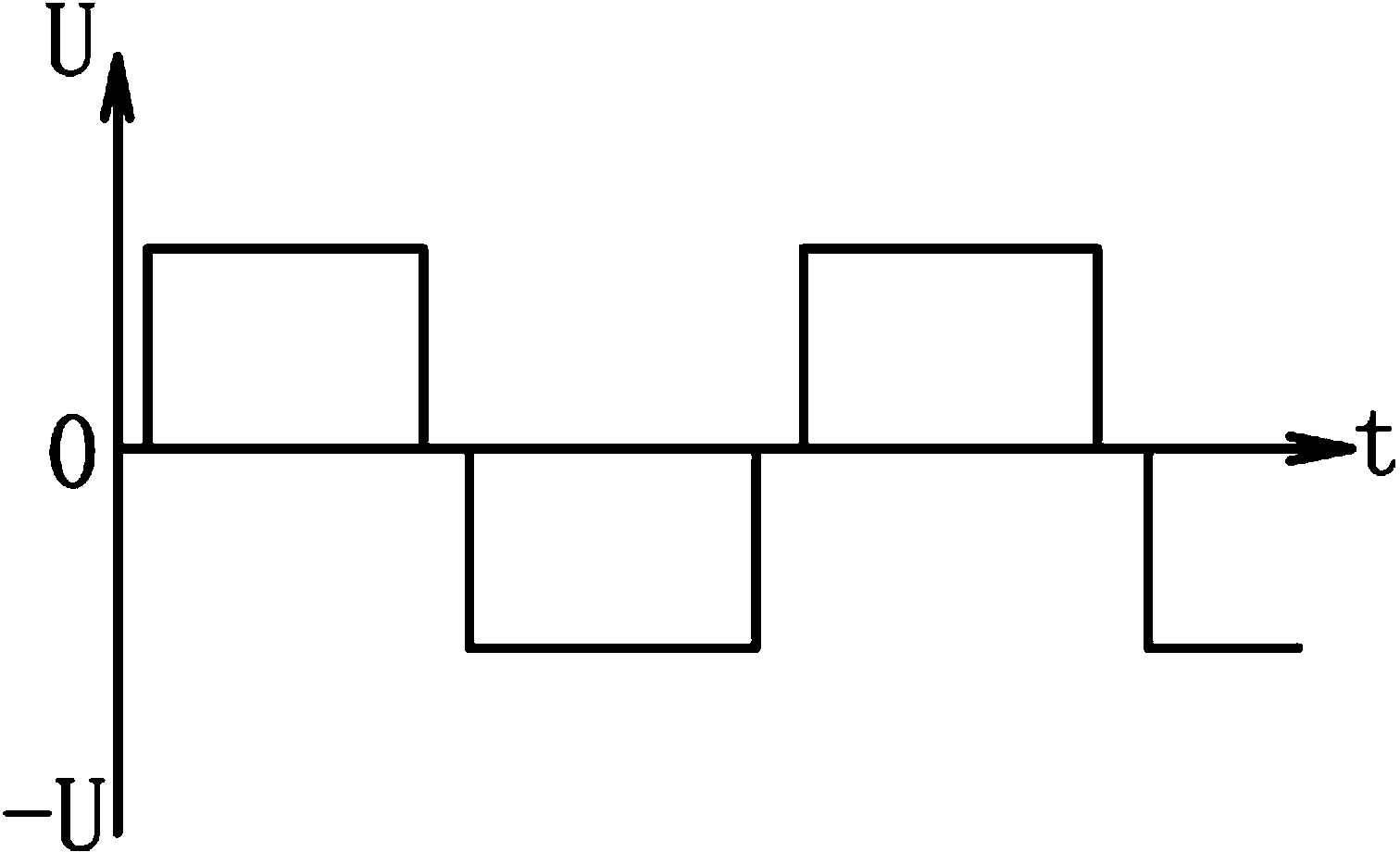
[0023] see figure 1 , figure 2 , image 3 , the driving method of the polymer-dispersed liquid crystal film of the present invention has a driving circuit electrically connected to two input electrodes of the polymer-dispersed liquid crystal film, and the driving circuit is applied on the polymer-dispersed liquid crystal film The drive voltage is a rectangular wave voltage that alternates between positive and negative, and the drive voltage quickly crosses zero and does not contain a DC component; the leading edge of the positive half-wave drive voltage output by the drive circuit is delayed by 1-10 microseconds, and the The leading edge of the negative half-wave driving voltage output by the driving circuit is delayed by 1-10 microseconds; the driving circuit includes a waveform signal generating circuit, a delay circuit, a driving stage and a switching circuit, and the driving circuit is electrically connected to a DC power supply circuit . In this embodiment, the prefer...
Embodiment 2
[0029] see figure 1 The DC power drive device of the polymer dispersed liquid crystal film of the present invention includes a DC power circuit 1, a boost circuit 2 and a drive circuit 3; the boost circuit includes a low voltage output circuit 201 and a high voltage output circuit 202; The drive circuit includes a waveform signal generation circuit 301, a delay circuit 302, a driver stage 303 and a switch circuit 304; the output terminals of the DC power supply circuit are electrically connected to the input terminals of the low voltage output circuit and the high voltage output circuit respectively, and the low voltage output circuit The output end of the voltage output circuit is electrically connected to the waveform signal generating circuit, the delay circuit, and the driver stage respectively, the output end of the high voltage output circuit is electrically connected to the switch circuit, and the output end of the waveform signal generating circuit is connected to the ...
PUM
 Abstract
Description
Claims
Application Information
 - R&D
- Intellectual Property
- Life Sciences
- Materials
- Tech Scout
- Unparalleled Data Quality
- Higher Quality Content
- 60% Fewer Hallucinations
Browse by: Latest US Patents, China's latest patents, Technical Efficacy Thesaurus, Application Domain, Technology Topic, Popular Technical Reports.
© 2025 PatSnap. All rights reserved.Legal|Privacy policy|Modern Slavery Act Transparency Statement|Sitemap|About US| Contact US: help@patsnap.com


