Stator

A stator and stator core technology, applied in electromechanical devices, electrical components, magnetic circuits, etc., can solve problems such as winding damage

Active Publication Date: 2013-01-02
GRUNDFOS HLDG
View PDF6 Cites 7 Cited by
  • Summary
  • Abstract
  • Description
  • Claims
  • Application Information

AI Technical Summary

Problems solved by technology

In addition, this construction requires that the shielding must be placed after the stator windings are installed
This makes it easy to damage the windings due to sharp plate parts or clips

Method used


Image

  • Stator
  • Stator
  • Stator

Examples


Embodiment Construction

[0068] Figure 12 A basic structure of the motor is shown. The stator 1 forms the stationary part of the electric machine and consists of a stator laminate 2 on which the windings 3 of the electric machine are arranged. In the region protruding beyond the stator lamination stack 2, the motor winding 3 forms the winding body 4, which is shielded from the rotor 5 which is rotatably mounted in the stator 1 by the shielding plate section 6 and thus prevents A current is induced in the shaft 7 of the rotor 5 via the stator winding 3 and is conducted via the bearing 8 in which the shaft 7 is mounted. The shielding plate segment 6 is electrically conductively connected to the stator lamination stack 2 , which in turn is electrically conductively connected to the grounded motor housing 9 .

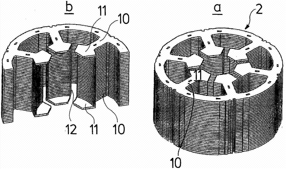
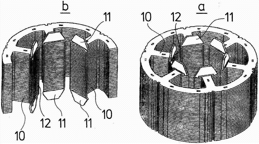
[0069] figure 1 and figure 2 It is shown how such a shielding section 6 , which is to electromagnetically shield the winding body 4 from the rotor 5 , is arranged next to the stator laminatio...


PUM


Abstract

The invention relates to a stator of an electric motor, including a stator lamination bundle (2) which is provided with windings (3) which pass through this and which in the regions projecting beyond the stator lamination bundle (2) form end-windings. An end-winding shielding which is electrically conductively connected to the stator lamination bundle (2) is provided. This shielding is formed by segmented and distanced shielding sections (6) which in each case shield at least one end-winding (4) completely or partly.

Description

technical field [0001] The invention relates to an electrical machine, in particular a stator of such an electrical machine, and a method of producing such a stator. Background technique [0002] A known problem with motors, especially frequency-controlled motors controlled with a frequency higher than the grid frequency, is the induction of voltages in the rotor, especially by the winding body of the stator, which generates a current through the motor shaft, The bearings connected to the motor shaft reach the motor housing and are gradually eliminated by short-circuiting. This current flow in the bearing area will cause wear and possibly premature failure of the bearing. In order to avoid this, in the prior art the stator winding is completely shielded from the rotor. [0003] Patent document US 5979087 proposes to provide conductive shields for the stator slots and in the region of the stator body, which are responsible for preventing this unwanted induction from the sta...

Claims


Application Information

Patent Timeline
Patent Type & Authority Applications(China)
IPC IPC(8): H02K3/42H02K1/14H02K3/34
CPCH02K15/022H02K3/522H02K3/325H02K11/0005H02K1/148Y10T29/49009H02K3/42H02K11/014
Inventor 托本·莫勒凯尔·赫勒加尔德
Owner GRUNDFOS HLDG
Why Eureka
Try Eureka