
Method and device for generating test signals of radio remote unit (RRU)

A technology for remote radio unit and test signal generation, which is applied in the field of network communication and can solve problems such as waste of signal source resources

Active Publication Date: 2013-01-02
ZTE CORP
View PDF4 Cites 11 Cited by
  • Summary
  • Abstract
  • Description
  • Claims
  • Application Information

AI Technical Summary

Problems solved by technology

In this way, after a large number of RRUs are generated, a large number of signal source instruments are required in order to improve the production test speed, and each signal source instrument only outputs a fixed mode signal, which causes a waste of signal source resources

Method used


Image

  • Method and device for generating test signals of radio remote unit (RRU)
  • Method and device for generating test signals of radio remote unit (RRU)
  • Method and device for generating test signals of radio remote unit (RRU)

Examples


Embodiment Construction

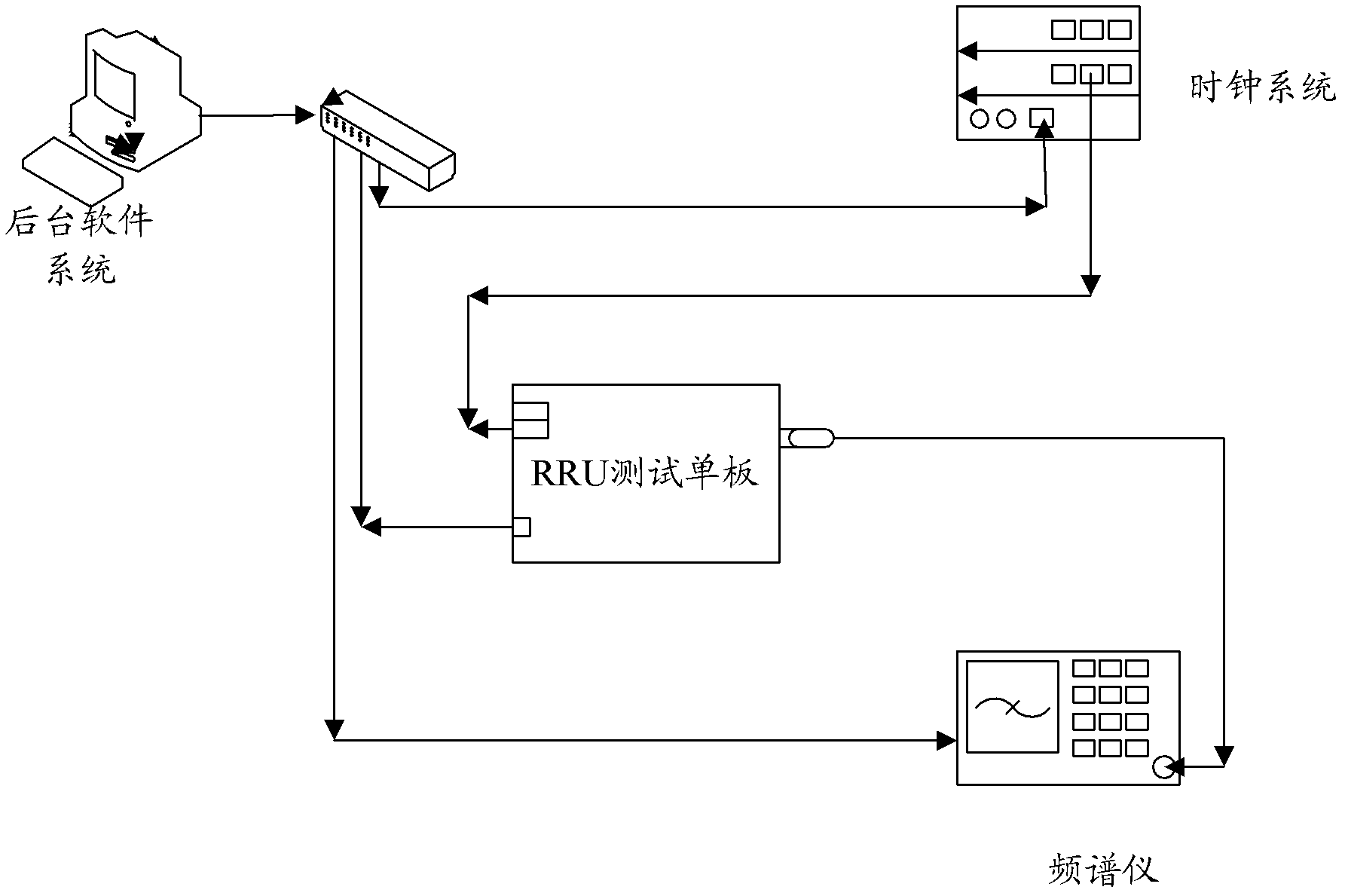
[0020] Since the RRU has the ability to transmit signals, in the embodiment of the present invention, the tested RRU is configured to generate a fixed pattern signal for testing the RRU, that is, to generate a test signal. In this way, the device for generating the RRU test signal composed of RRUs can serve as a signal source in the RRU test process, thereby eliminating the need for complex function signal source instruments in the prior art, and greatly saving test resources in the RRU test process.

[0021] The device for generating the RRU test signal in the embodiment of the present invention can be represented by an RRU test single board, see figure 1 , the device includes: a receiving unit 100, a configuration unit 200 and an RRU300, wherein,

[0022] The receiving unit 100 is configured to receive an output signal message in the current test mode.

[0023] The configuration unit 200 is configured to set the value of the downlink numerically controlled attenuator in the...


PUM


Abstract

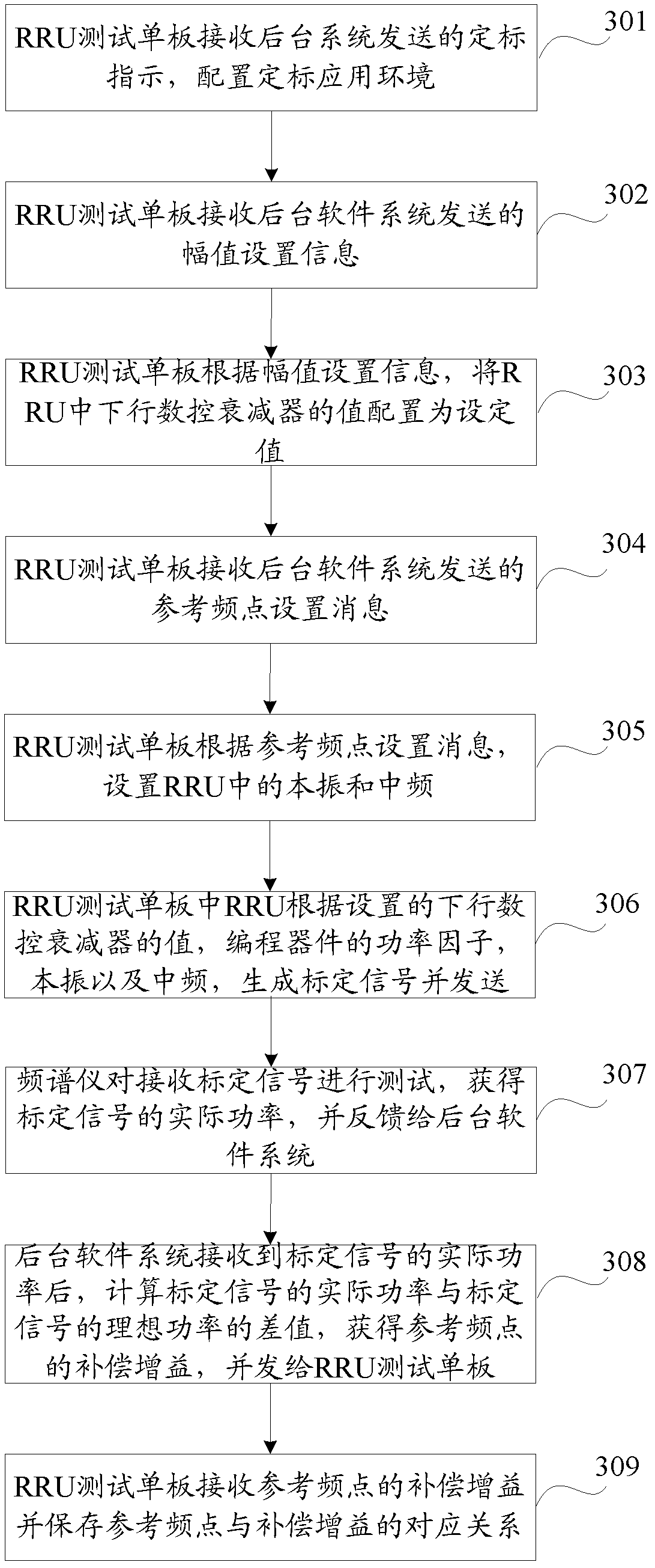
The invention discloses a method and a device for generating test signals of a radio remote unit(RRU) and aims to save test resources in a RRU testing process. The method includes receiving output signal message in a current testing mode; setting value of a downlink digital attenuator in the RRU according to amplitude of the output signal message; acquiring first compensation gain corresponding to a working frequency point in the output signal message according to corresponding relation between stored reference frequency point and compensation gain, and setting power factor of a program device in the RRU according to the acquired first compensation gain; and finally generating the test signals corresponding to the current testing modes by the RRU according to the value of the downlink digital attenuator and the power factor of the program device.

Description

technical field [0001] The invention relates to the technical field of network communication, in particular to a method and device for generating a test signal of a radio remote unit. Background technique [0002] The remote radio unit (Remote Radio Unit, RRU) is a new type of distributed network coverage mode. It places large-capacity macrocell base stations centrally in the available central equipment room. The baseband part is processed centrally. Optical fibers are used to connect the The radio frequency module is pulled to the remote radio frequency unit and placed on the site determined by the network planning, thereby saving a large number of computer rooms required by conventional solutions; at the same time, by using a large-capacity macro base station to support a large number of remote optical fibers, the capacity and Conversion between overlays. [0003] After the RRU is produced, it needs to be tested for uplink receiving data, and it can be put into use only a...

Claims


Application Information

Patent Timeline
Patent Type & Authority Applications(China)
IPC IPC(8): H04B17/00H04W88/08
CPCH04W88/085H04B17/00H04W24/04H04W88/08
Inventor 王清源晏梦君董超
Owner ZTE CORP
Learn More