Ultrasonic wave welding line structure, welding method, product casing and electronic product

A technology of ultrasonic welding and electronic products, applied in the direction of electrical equipment shell/cabinet/drawer, electrical components, chassis/box/cabinet/drawer parts, etc., which can solve the problems of increasing welding control complexity and increasing mold processing cost. , to achieve the effect of reducing complexity, reducing requirements and reducing production costs

Inactive Publication Date: 2013-01-02
LAIRD ELECTRONICS MATERIALS CO LTD
View PDF4 Cites 9 Cited by
  • Summary
  • Abstract
  • Description
  • Claims
  • Application Information

AI Technical Summary

Problems solved by technology

[0010] However, the matching structure of the wedge-shaped groove and the wedge-shaped protrusion requires high dimensional matching accuracy, which puts high demands on the design and manufacture of the mold and in

Method used


Image

  • Ultrasonic wave welding line structure, welding method, product casing and electronic product
  • Ultrasonic wave welding line structure, welding method, product casing and electronic product
  • Ultrasonic wave welding line structure, welding method, product casing and electronic product

Examples


Embodiment Construction

[0039] Attached below Figure 3-7 , to describe the details of specific embodiments of the present invention in detail. However, it should be noted that the following description is merely exemplary in nature and is not intended to limit the disclosure, application or use of the present invention.

[0040] Certain terms used in the following description are for reference only and thus are not meant to be limiting. For example, terms such as "upper," "lower," "top," and "bottom" refer to directions in the drawings to which reference is made.

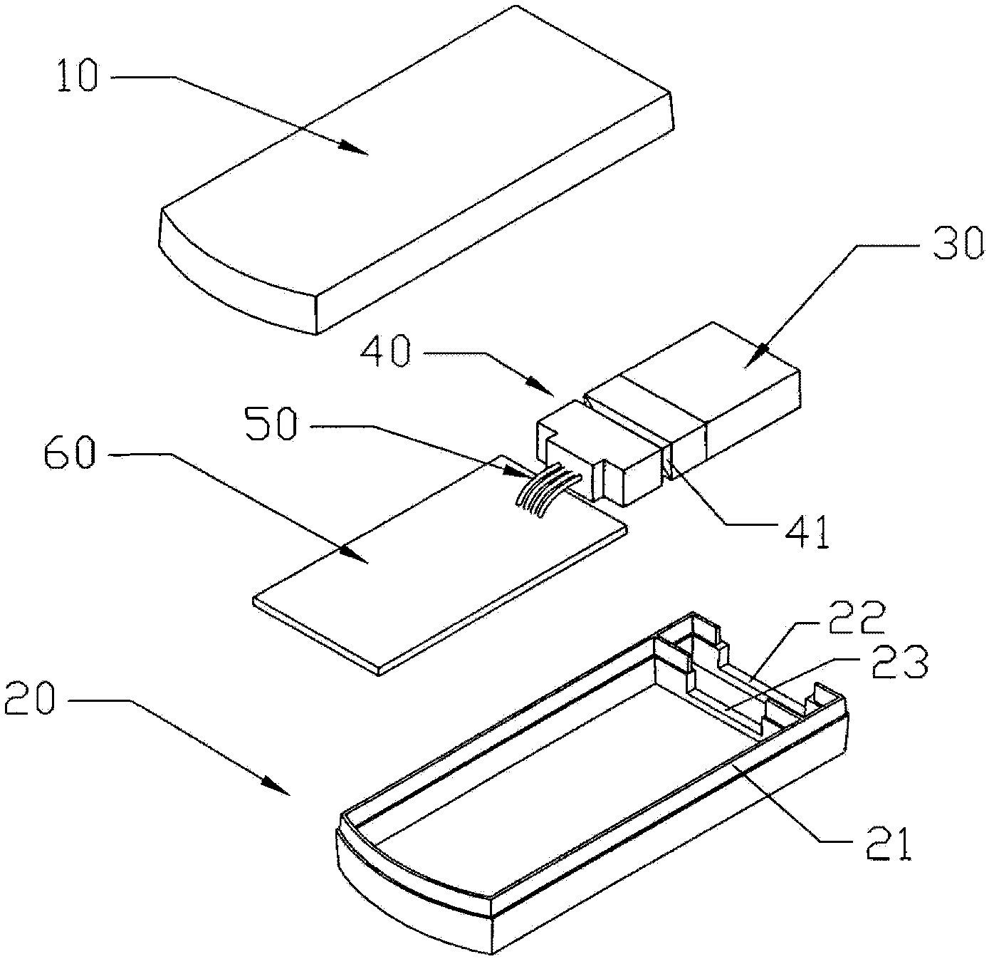
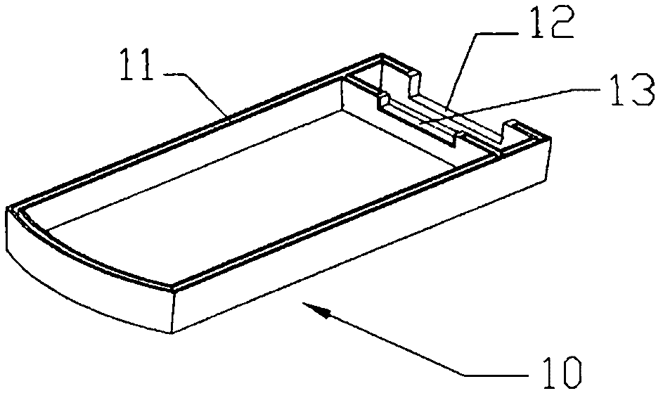
[0041] Such as image 3 and Figure 4 As shown, one embodiment of the present invention relates to a loudspeaker module. The loudspeaker module includes an upper casing 1 and a lower casing 2 , and components such as a speaker 3 and a flexible printed circuit board (FPC) 4 are packaged in the product casing composed of the upper and lower casings 1 and 2 .

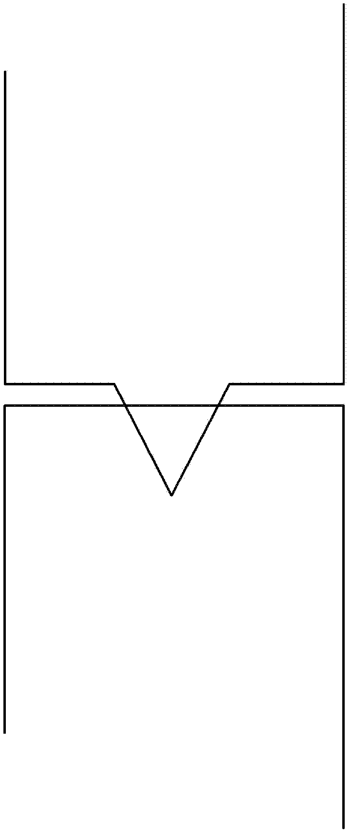
[0042] Such as Figure 5A and Figure 5B As shown, in the process of assem...


PUM


Abstract

The invention provides an ultrasonic wave welding line structure which includes that an ultrasonic wave welding line is formed on the assembly surface of one semi-casing which forms a product casing and is provided with an upper semi-casing and a lower semi-casing which are provided with assembly surfaces respectively, a matching line is formed on the assembly surface of the other semi-casing of the upper semi-casing and the lower semi-casing, and the matching line and the ultrasonic wave welding line are partially matched in shape. A section of the ultrasonic wave welding line is in a shape protruding from the assembly surface of one semi-casing, the section of the matching line is in a step shape concaving from the assembly surface of the other semi-casing, the concaved portion of the step shape extends to the inner edge of the assembly surface of the other semi-casing, and the height of a protrusion relative to the assembly surface of one semi-casing is larger than the height of a step relative to the assembly surface of the other semi-casing.

Description

technical field [0001] The invention relates to an ultrasonic welding profile structure, which includes an ultrasonic welding profile and a matching profile respectively formed on the assembly surfaces of an upper half shell and a lower half shell constituting a product shell, and the matching profile and ultrasonic welding The profile partially constitutes a form fit. Background technique [0002] At present, many electronic products, such as speaker modules used in communication equipment such as mobile phones, usually have a casing composed of two half-shells for encapsulating electronic devices inside. The two half-shells are welded together during assembly, often by means of ultrasonic welding. [0003] Ultrasonic welding is a welding method that uses high-frequency vibration waves to transmit to the surfaces of two objects to be welded. Under pressure, the surfaces of the two objects are rubbed against each other to form fusion between molecular layers. [0004] Usua...

Claims


Application Information

Patent Timeline
IPC IPC(8): H05K5/02H05K5/00B29C65/08
Inventor 陈柏志蔡欣昀
Owner LAIRD ELECTRONICS MATERIALS CO LTD
Why Eureka
Try Eureka