Air guide cover

A technology of wind deflector and buckle parts, which is applied in the field of wind deflector and can solve the problems that the wind deflector is difficult to assemble on electronic devices, etc.

Inactive Publication Date: 2013-01-02
INVENTEC CORP
View PDF0 Cites 3 Cited by
  • Summary
  • Abstract
  • Description
  • Claims
  • Application Information

AI Technical Summary

Problems solved by technology

[0004] In view of the above problems, the object of the present invention is to provide a wind deflector, so as t

Method used


Image

  • Air guide cover
  • Air guide cover
  • Air guide cover

Examples


Embodiment Construction

[0053] Below in conjunction with accompanying drawing, structural principle and working principle of the present invention are specifically described:

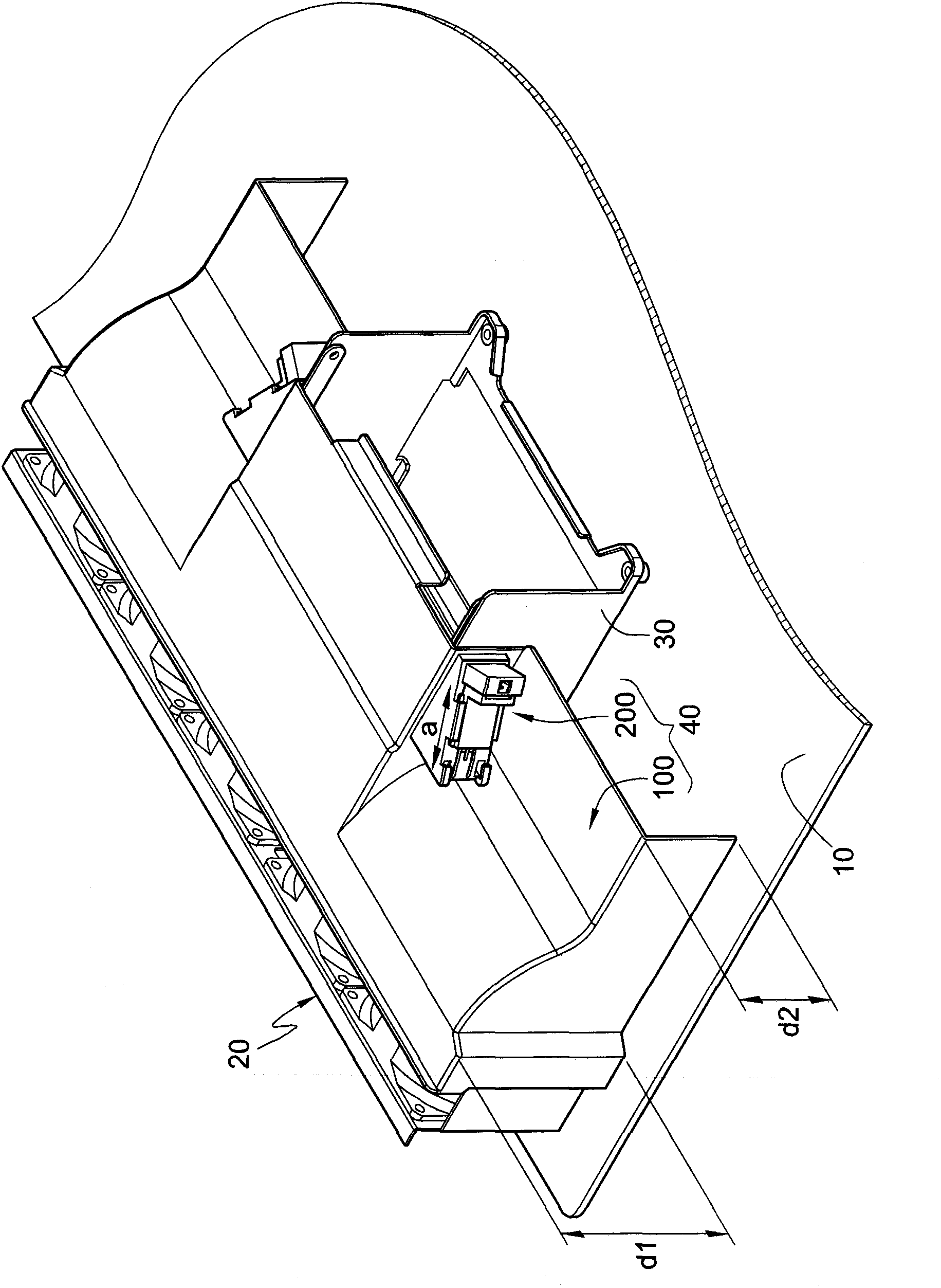
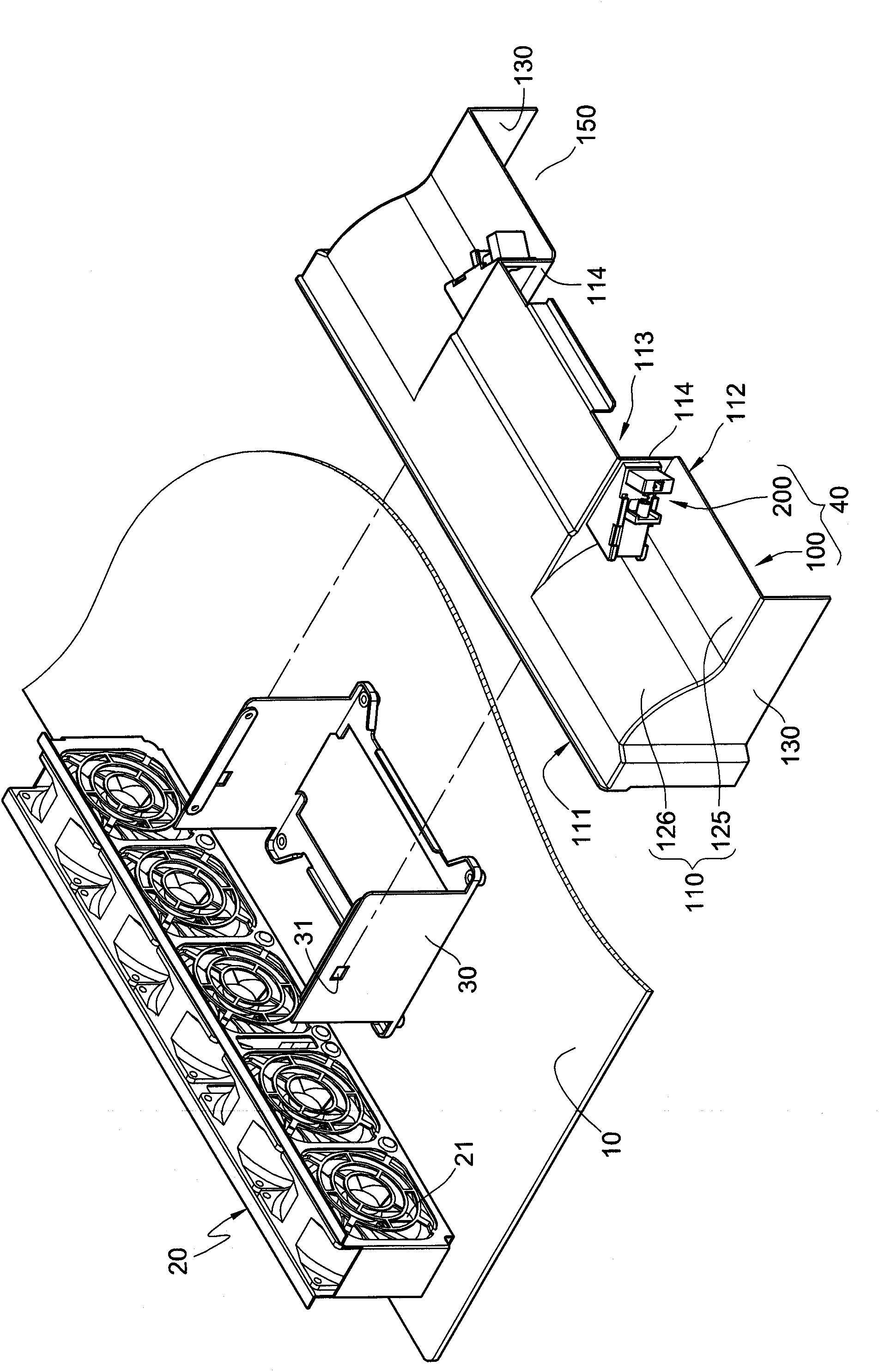
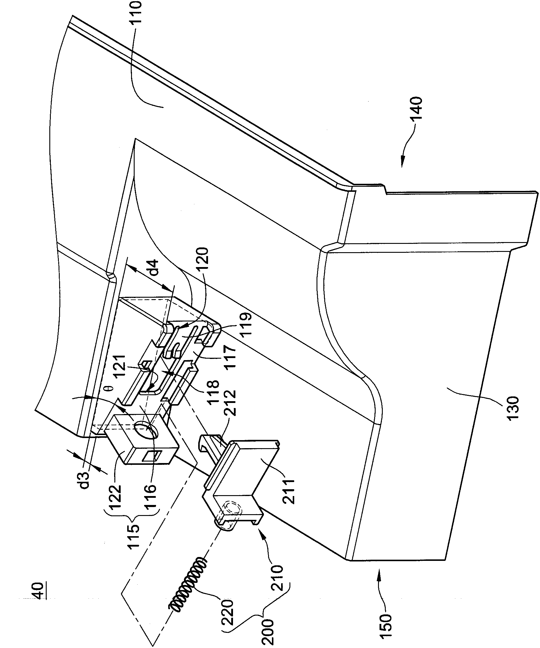
[0054] Please also see Figure 1A to Figure 3 , Figure 1A It is a three-dimensional schematic diagram of the combination of the air guide cover with the housing equipped with the fixing frame and the fan according to the first embodiment disclosed in the present invention, Figure 1B for Figure 1A The three-dimensional schematic diagram of the wind deflector detached from the housing equipped with a fixed frame and a fan, figure 2 for Figure 1A An exploded schematic diagram of the air duct, image 3 for Figure 1A A three-dimensional schematic diagram of another perspective of the windshield. The casing 10 referred to above is a motherboard inside an electronic device, such as a server, a desktop computer or a notebook computer. A fan module 20 and a fixing frame 30 are disposed on the housing 10 . The fixing frame 30 i...


PUM


Abstract

The invention discloses an air guide cover, comprising a cover body and a pair of buckling modules. The cover body is provided with a heat radiation module containing groove and a pair of buckling grooves; the buckling module is provided with a clamping part; the heat radiation module containing groove is provided with a pair of opposite lateral walls; and the pair of the buckling grooves and the pair of the lateral walls respectively form acute angles, so that a containing space is defined by each buckling groove and each lateral wall. When the buckling module is located at a released position, the buckling parts are located in the containing spaces. When the buckling module is located at a buckling position, the buckling part partially extends out of the containing spaces to be combined on a fixing frame.

Description

technical field [0001] The invention relates to an air guide cover, in particular to an air guide cover that can be quickly assembled on a fixing frame. Background technique [0002] In recent years, fans are often used in electronic devices. When the fan is running, the fan will generate a forced convection in the electronic device. This forced convection is used to suck the cold air outside the electronic device into the electronic device, and make the sucked cold air absorb the heat inside the electronic device and heat it up. air, which then vents the hot air out of the electronics. However, when the heat emitted by the electronic device is higher, the power of the fan needs to be higher to extract a larger amount of gas to exchange heat with the higher heat generated by the electronic device, thereby maintaining the temperature of the electronic device at within the safe temperature range. However, the higher the power of the fan, the louder the noise and the more po...

Claims


Application Information

Patent Timeline
IPC IPC(8): H05K7/20G06F1/20
Inventor 陈永崇
Owner INVENTEC CORP
Why Eureka
Try Eureka