

Dishwasher
A tableware washing machine and washing water technology, applied in the direction of tableware washing machine/rinsing machine, tableware washing machine/rinsing and rinsing machine parts, cleaning equipment, etc., which can solve the problem of insufficient nozzle rotation and insufficient rotation of tower nozzle 55 , small torque, etc.
- Summary
- Abstract
- Description
- Claims
- Application Information
AI Technical Summary
Problems solved by technology
Method used
Image

Examples
Embodiment approach 1
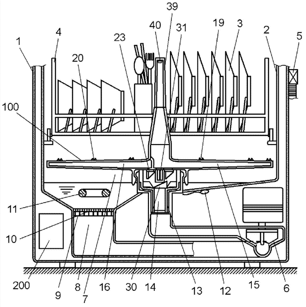
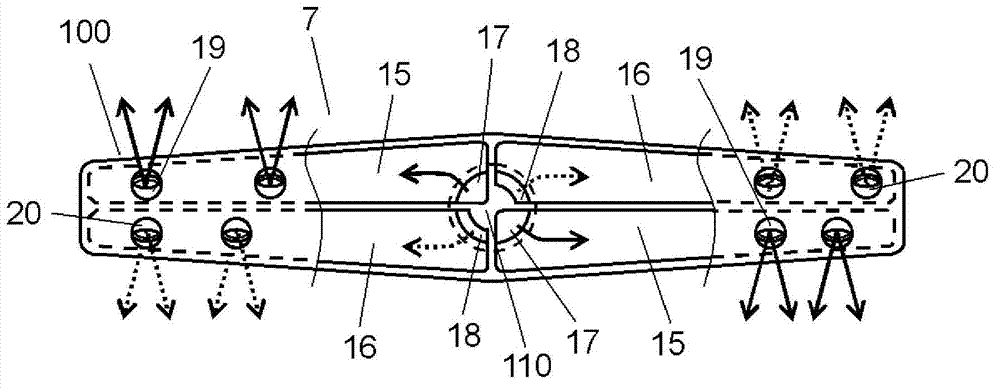
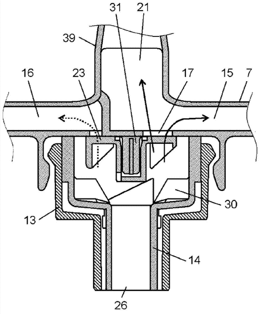
[0027] figure 1 It is a schematic sectional view of the dishwasher according to Embodiment 1 of the present invention. figure 2 It is a partial cross-sectional view of the washing nozzle of the dishwasher according to Embodiment 1 of the present invention viewed from above. image 3 It is a cross-sectional view of a part of the washing nozzle and a valve body of the dishwasher according to Embodiment 1 of the present invention. Figure 4 It is a perspective view of main parts of the dishwasher according to Embodiment 1 of the present invention. Figure 5 It is a main part perspective view of the dishwasher of Embodiment 1. Figure 6 It is a perspective view of the valve body of the dishwasher of Embodiment 1. Figure 7 It is a plan view of the valve body of the dishwasher of Embodiment 1. Figure 8 It is a bottom view of the valve body of the dishwasher of Embodiment 1. Figure 9 It is a partial sectional view of the vicinity of the valve body of the dishwasher of Embod...
Embodiment approach 2
[0056] Figure 11 It is a top view of the washing nozzle channel inlet and the tower nozzle channel inlet 22 of the dishwasher according to Embodiment 2 of the present invention. Figure 12 It is a cross-sectional view of a part of washing nozzle 7 and valve body 23 of the dishwasher according to Embodiment 2 of the present invention. Figure 13 It is a top view of the state where the valve body 23 of the dishwasher according to Embodiment 2 of the present invention is in contact with the inlet of the flow path of the washing nozzle and the inlet of the flow path of the tower nozzle. Figure 14 It is viewed from the tower nozzle 39 side Figure 13 The cross-sectional view obtained from the top view. Figure 15 It is a cross-sectional view of washing nozzle 7 and tower nozzle 39 of the dishwasher according to Embodiment 2 of the present invention. Figure 16 It is a sectional view which looked at the tower nozzle 39 of the dishwasher concerning Embodiment 2 of this invention...
PUM
 Abstract
Description
Claims
Application Information