
Transmission apparatus for remotely indicating position and reception apparatus

A technology of transmitting equipment and receiving equipment, which is applied in the field of remote control position indication system, and can solve the problems that the transmitting equipment cannot be implemented.

Inactive Publication Date: 2013-01-02
蔡光默
View PDF4 Cites 76 Cited by
  • Summary
  • Abstract
  • Description
  • Claims
  • Application Information

AI Technical Summary

Problems solved by technology

Therefore, a transmitter device that indicates the position remotely is not feasible

Method used


Image

  • Transmission apparatus for remotely indicating position and reception apparatus
  • Transmission apparatus for remotely indicating position and reception apparatus
  • Transmission apparatus for remotely indicating position and reception apparatus

Examples


Embodiment Construction

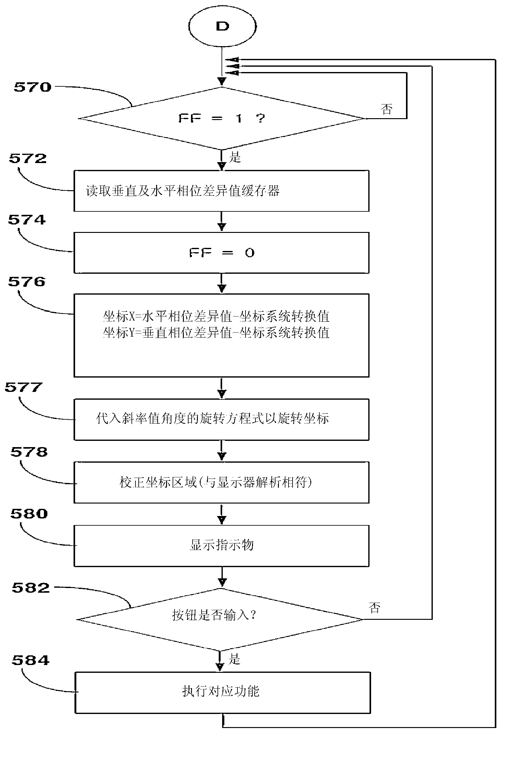
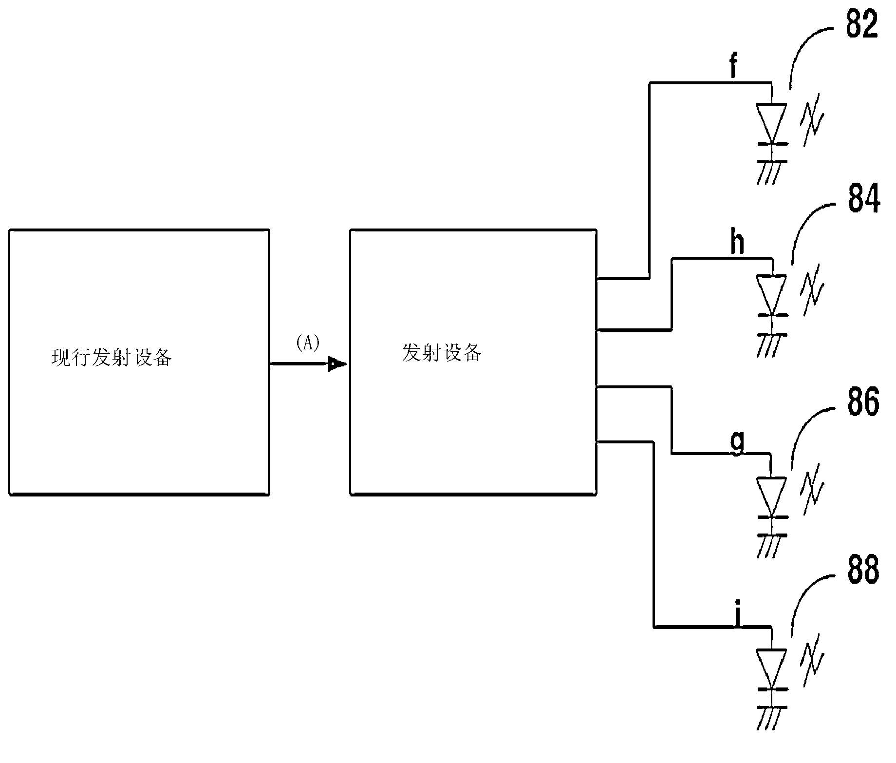
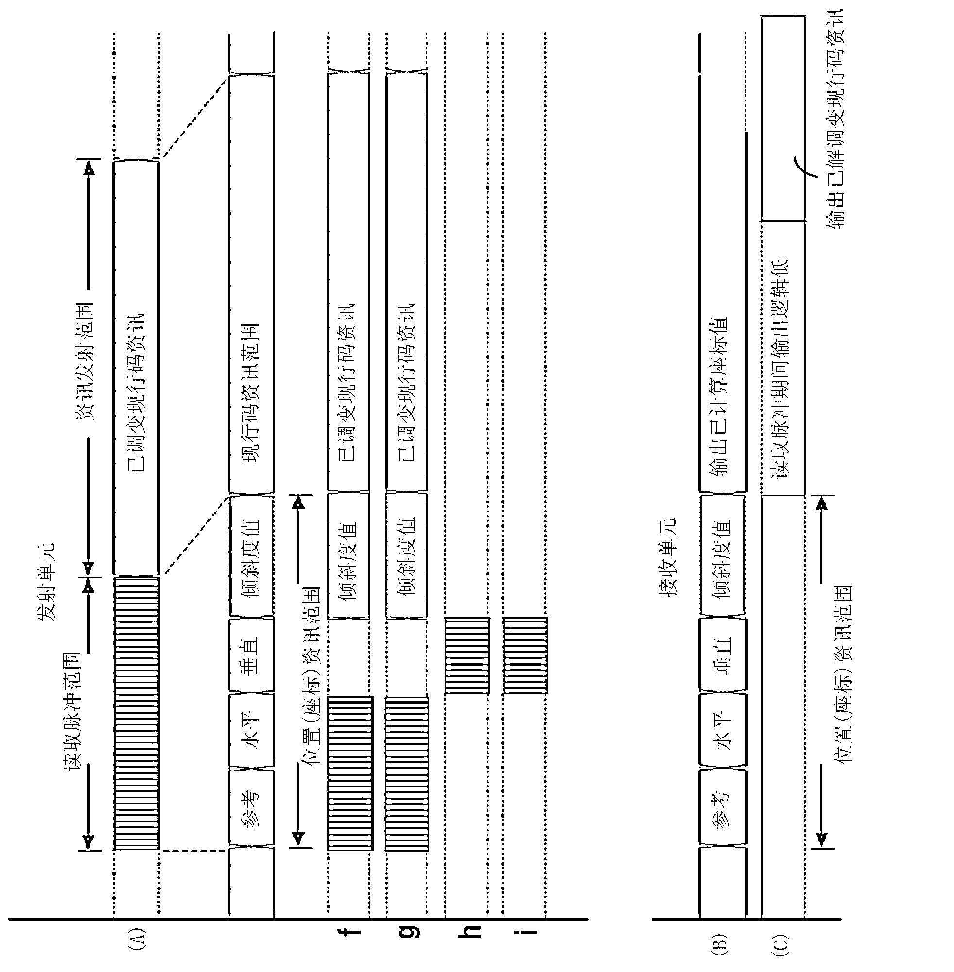
[0032] Hereinafter, representative embodiments of the present invention will be described along with the accompanying drawings. In the following description, the same components will be indicated by the same reference numerals even though the same components are shown in different drawings. Furthermore, in the following description of the present invention, when a detailed description of known functions or structures incorporated herein may obscure the subject matter of the present invention, it will be omitted.

[0033] In addition, items such as first, second, A, B, (a), (b), etc. may be used herein when describing components of the present invention. These terms are not used to define the nature, rules or sequences of the corresponding components, but are only used to distinguish the corresponding components from other components. It should be noted that if it is described in the specification that one component is "connected", "coupled" or "combined" with another componen...


PUM


Abstract

The present invention relates to a position-indicating transmission apparatus capable of being remotely controlled, and a reception apparatus. The transmission apparatus transmits waveforms of same frequencies having different phase angles simultaneously and includes a means for measuring an inclined angle of a transmitter with respect to an axis of terrestrial gravity to measure and transmit the inclined value of the transmitter. The reception apparatus receives and amplifies the transmitted signals and processes the amplified signals to obtain the position information related to the variation of the shifted phases with respect to the reference signal. The present invention responds easily to an input corresponding to a movement of a user or a shift in the visual field of a cursor, and has practical application in electronic devices such as TV's, computers, VCR's, LDP's, DVD players, various kinds of VOD systems, IP TV's and cable TV terminals, various kinds of communication terminals, home game consoles, computers for use with infants, HMD (Head Mount Display) devices, and the like.

Description

technical field [0001] The present invention relates to a transmitting device and a receiving device for marking a position at a distance, in particular to a remotely controlled position indication system consisting of a transmitting device comprising a device for measuring the angle tending to be related to the gravitational axis means, and contact switches for emitting waveforms with different phase angles but the same frequency. The receiving device is used to receive and process the signal transmitted by the transmitting device. Background technique [0002] In general, in addition to remotely controlling the transmitting device (such as a remote controller), a transmitting device that utilizes the directional direction of the transmitting device as the remote position information in the subject monitor to remotely indicate the position has been developed. [0003] The transmitting device used for long-distance indication of position usually transmits signals to various...

Claims


Application Information

Patent Timeline
Patent Type & Authority Applications(China)
IPC IPC(8): H04Q9/06H04Q9/14H04Q9/04
CPCG08C21/00H04Q9/04H04Q9/06H04Q9/14
Inventor 蔡光默
Owner 蔡光默
Learn More