
Steel twisted rope reeling off device

A rope release device and steel strand rope technology, which is applied in the field of steel strand rope release device, can solve the problems of personal injury of operators, complicated stress, and high strength of steel strand rope, etc.

Inactive Publication Date: 2013-01-09
HUAINAN MINING IND GRP
View PDF6 Cites 2 Cited by
  • Summary
  • Abstract
  • Description
  • Claims
  • Application Information

AI Technical Summary

Problems solved by technology

[0003] There are at least the following problems in the prior art: firstly, the strength of the steel strand itself is very high, and the elastic force is also very large during its natural unfolding, which is likely to cause personal injury to the operator; secondly, the steel strand is naturally unfolded. During the process, the force is complicated, and the steel strands are easy to twist together, making it impossible to cut

Method used


Image

  • Steel twisted rope reeling off device
  • Steel twisted rope reeling off device
  • Steel twisted rope reeling off device

Examples


Embodiment 1

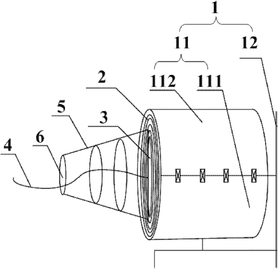
[0045] figure 1 It is a schematic diagram of the steel strand rope releasing device provided by Embodiment 1 of the present invention. Embodiment 1 of the present invention provides a steel strand rope unwinding device, which includes a fixing device 1, the fixing device 1 is used to surround the outer side of the steel strand rope roll 2 coiled in coils, and limit the radial expansion of the steel strand rope roll 2; A steel strand rope outlet 3 is provided on the fixing device 1, and the steel strand rope outlet 3 is used to stretch out the steel strand rope 4 of the steel strand rope roll 2, so that the steel strand rope 4 stretched out from the center of the steel strand rope roll 2 to The edges spread out.

[0046] On the basis of the above-mentioned technical scheme, preferably: the steel strand rope release device also includes a resistance device, the resistance device is fixedly connected with the end face of the fixing device 1, and is located outside the steel stra...

Embodiment 2

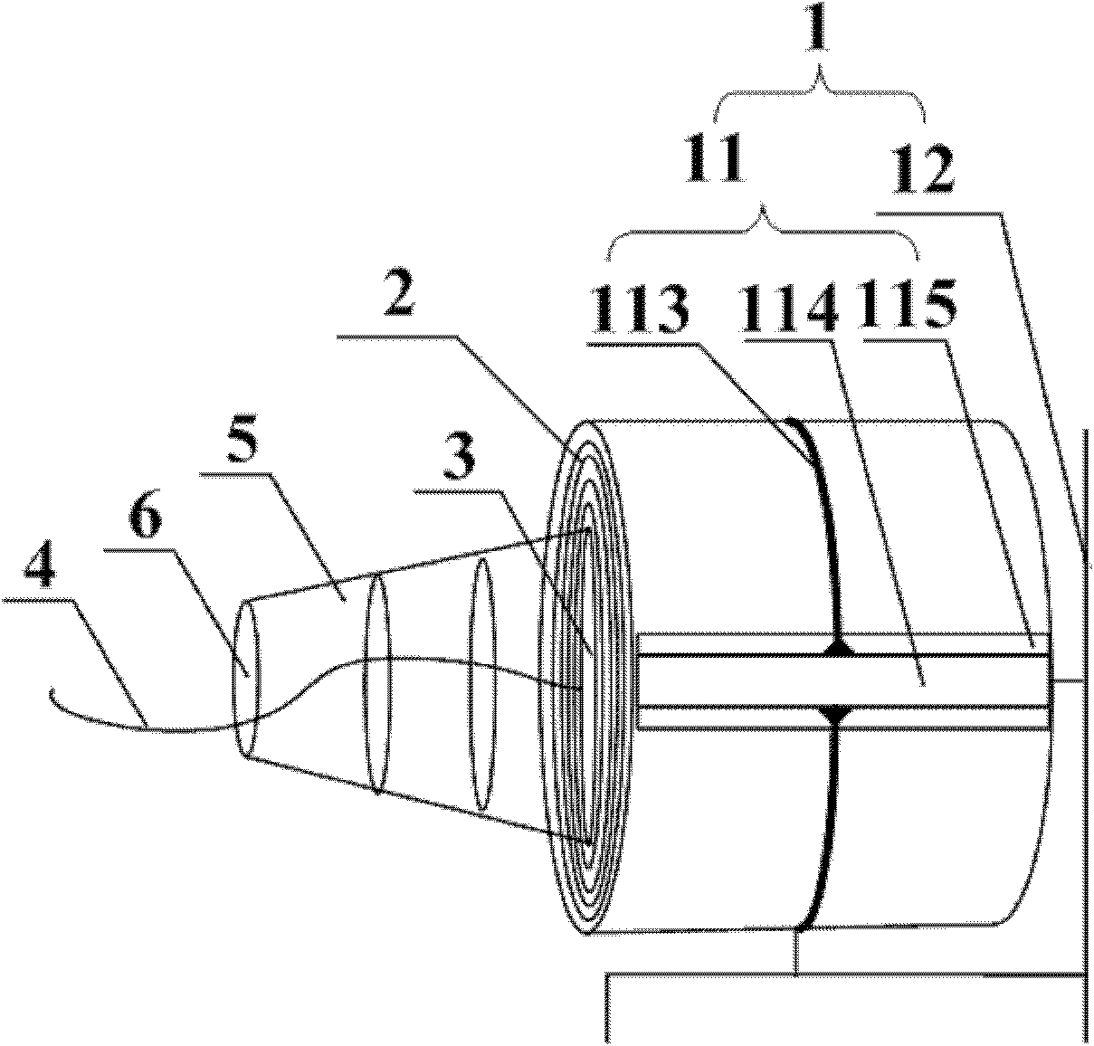
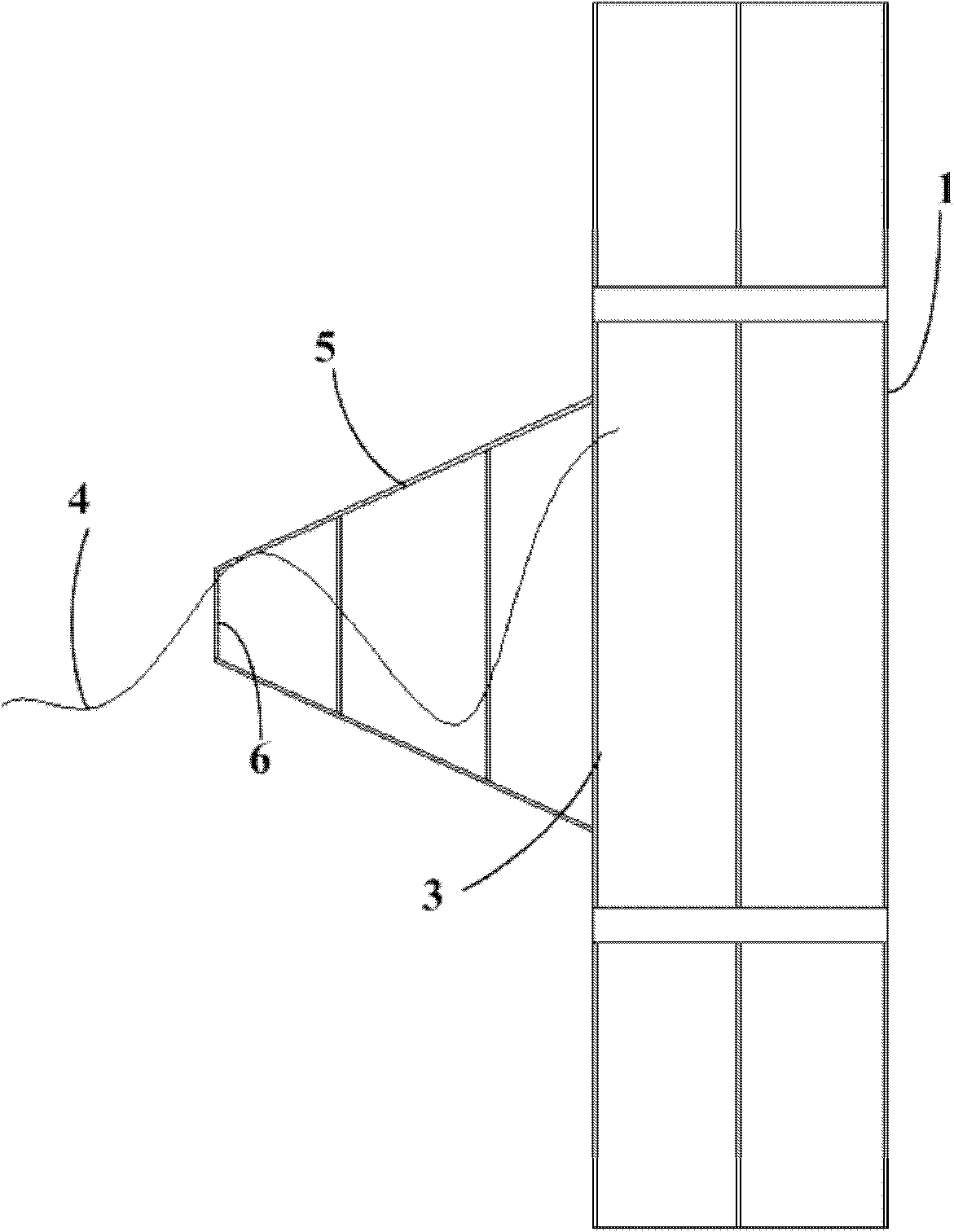
[0058] Figure 2AIt is a schematic diagram of the steel strand rope releasing device provided by Embodiment 2 of the present invention. Figure 2B for Figure 2A A schematic top view of the part. Figure 2C for Figure 2A Partial left view schematic diagram of . The difference between the second embodiment of the present invention and the first embodiment lies in that the implementation of the steel strand fixing structure 11 is different. In this embodiment, the steel strand fixing structure 11 includes several circular arc rods 113 and several connecting channel steels 114; Intersect to form a cylindrical press frame; the length of the connecting channel steel 114 along the axial direction of the steel strand rope roll 2 is not less than the stacking height of the steel strand rope roll 2 .

[0059] The structure of the arc rod and the connecting channel steel is simple, which is convenient for processing and manufacturing, and the formed cylindrical press frame is light...


PUM


Abstract

The invention discloses a steel twisted rope reeling off device, wherein the device comprises a fixing device which is used for surrounding at the outer side of a steel twisted rope coil which is coiled as a reel and is used for limiting the radial expansion of the steel twisted rope coil; a steel twisted rope outlet is arranged on the fixing device; through the steel twisted rope outlet, the steel twisted rope of the steel twisted rope coil stretches out, so that the stretched steel twisted rope expands towards the edge from the center of the steel twisted rope coil. According to steel twisted rope reeling off device, the radial expansion of the steel twisted rope coil is limited and the steel twisted rope expands towards the edge from the center of the steel twisted rope coil owing to the fixing device, so that personnel injury on the operator because of great elasticity in a process that the steel twisted rope naturally expands is avoided; meanwhile, the phenomenon that the steel twisted rope cannot cut due to the fact that the steel twisted rope is twisted in the expanding process.

Description

technical field [0001] The invention relates to mechanical structure technology, in particular to a steel strand rope releasing device. Background technique [0002] A product often used in mine operations is steel strand rope for prestressed concrete. The steel strand rope is packaged in rolls and must be cut before use. The current cutting method is to let the steel strand rope unfold naturally, and then It cuts. [0003] There are at least the following problems in the prior art: firstly, the strength of the steel strand itself is very high, and the elastic force is also very large during its natural unfolding, which is likely to cause personal injury to the operator; secondly, the steel strand is naturally unfolded. During the process, the force is complicated, and the steel strands are easily twisted together, making it impossible to cut. Contents of the invention [0004] The invention provides a steel strand rope unwinding device, which is used to improve the safe...

Claims


Application Information

Patent Timeline
Patent Type & Authority Applications(China)
IPC IPC(8): B65H49/06B65H57/06
Inventor 魏博王永谢一多于刘路程晋孝胡文卫
Owner HUAINAN MINING IND GRP
Learn More