Disc dehydration unit

A disc dehydration and locking device technology, applied in the field of dehydration devices, can solve the problems of high power required for drum dehydrator rotation, dehydration time of less than 30 seconds, and poor dehydration effect of granulated slag. Low moisture content of product slag, simple structure and long service life

Active Publication Date: 2013-01-09
BERIS ENG & RES CORP
View PDF5 Cites 0 Cited by
  • Summary
  • Abstract
  • Description
  • Claims
  • Application Information

AI Technical Summary

Problems solved by technology

But at present, when the drum type dehydrator rotates once for dehydration, a batch of granulated slag is dehydrated, and its real dehydration time is less than half of the dehydrator's one-week time. Generally, the dehydrator rotates at 1 revolution per minute, so the dehydration time is less than 30 seconds, the dehydration effect of the granulated slag is not good, and the moisture content of the finished slag reaches more than 30%
[0003] In addition, the rotation of the drum dehydrator requires a large amount of power, generally reaching hundreds of kilowatts, and the power consumption is relatively large.
Moreover, when the dehydrator unloads slag, there is relative movement between the slag and the dehydrator. Since the frequency of slag unloading in the drum type dehydrator is very high, the wear on the dehydrator is relatively severe, and the life of the dehydrator is short.

Method used


Image

  • Disc dehydration unit
  • Disc dehydration unit
  • Disc dehydration unit

Examples


Embodiment Construction

[0021] In order to better understand the purpose, structure and function of the present invention, a disk dehydration device of the present invention will be further described in detail below in conjunction with the accompanying drawings.

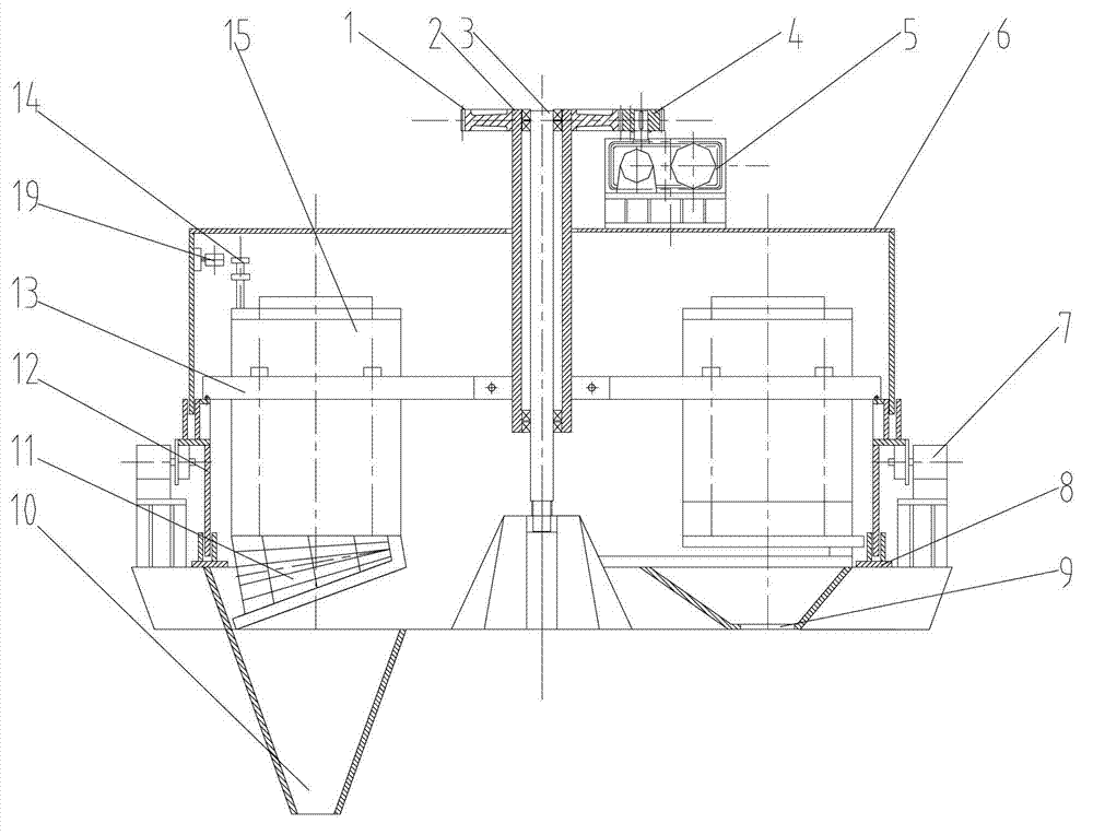
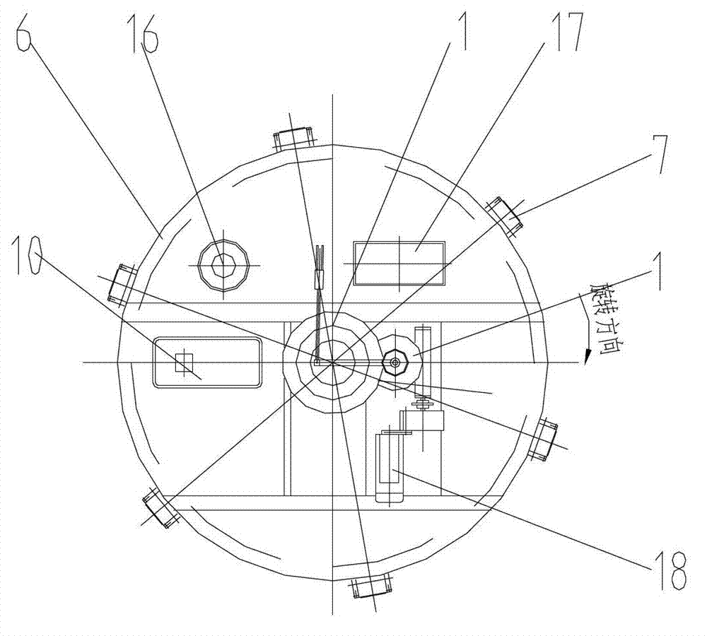
[0022] like figure 1 As shown, the disk dehydration device of the present invention includes a central pillar 3 and a rotating cylinder 12 rotating around the central pillar 3, wherein the upper part of the rotating cylinder 12 is provided with an upper cover 6, and the lower part is provided with a lower shell 8. The top of the upper cover 6 is provided with a material inlet 16 and a transmission part for driving the rotating cylinder 12 to rotate, and the bottom of the lower shell 8 is provided with a material outlet 10 .

[0023] Specifically, the upper cover 6, the lower shell 8 and the central pillar 3 in the present invention are all arranged on a fixed foundation (not shown in the figure), while the rotating cylinder 12 is supported ...


PUM


Abstract

The invention discloses a disc dehydration unit which comprises a central column (3) and a rotating cylinder (12) which rotates around the central column (3), wherein a plurality of sieve hoppers (15) are arranged in the rotating cylinder (12) and a sieve plate (11) which can automatically close and open is connected to the bottom of each of the sieve hoppers (15). According to the disc dehydration unit, the design is reasonable, the structure is simple, the failure rate is low, the overhaul is convenient, and the service life is long. Water slag dehydration time is long, the moisture content of product slag is low, and the unit is applicable to various blast furnaces, no sewage is discharged, and the unit is environment-friendly.

Description

technical field [0001] The invention relates to a dehydration device, in particular to a water quenching slag treatment dehydration device. Background technique [0002] Metallurgy, chemical industry, non-ferrous metals and other industries generally use water quenching to treat slag, and drum dehydration devices have become the absolute mainstream. But at present, when the drum type dehydrator rotates once for dehydration, a batch of granulated slag is dehydrated, and its real dehydration time is less than half of the dehydrator's one-week time. Generally, the dehydrator rotates at 1 revolution per minute, so the dehydration time is less than For 30 seconds, the dehydration effect of the granulated slag is not good, and the moisture content of the finished slag reaches more than 30%. [0003] In addition, the rotation of the drum dehydrator requires a large amount of power, generally reaching hundreds of kilowatts, and the power consumption is relatively large. Moreover, ...

Claims


Application Information

Patent Timeline
Patent Type & Authority Applications(China)
IPC IPC(8): C21B3/08
CPCC21B2400/032
Inventor 赵祉荣贺春平
Owner BERIS ENG & RES CORP
Why Eureka
Try Eureka