Tension and compression coupling type high-strength and high-deformation anchor rod and method for using same

A large-deformation, coupling-type technology, applied in the installation of bolts, earthwork drilling, sheet pile walls, etc., can solve the problems of large-deformation bolts with complex structures, difficult to reach, high bearing capacity, etc., to improve reliability and support The effect of protecting, optimizing the stress state, and improving the effect of supporting resistance

Active Publication Date: 2015-04-08
SHANDONG UNIV OF SCI & TECH
View PDF11 Cites 0 Cited by
  • Summary
  • Abstract
  • Description
  • Claims
  • Application Information

AI Technical Summary

Problems solved by technology

However, the bearing capacity of the inner anchorage section is limited by the compressive strength of the anchoring agent itself and the shear strength between the anchoring agent and the hole wall, so it is difficult to achieve a higher bearing capacity
[0006] In order to make the anchor rod have a large deformation property, the current large deformation anchor rod generally realizes the deformation of the anchor rod by setting mechanical structures such as friction sleeves and sliding between the rod body and these structural elements, such as Chinese patents CN 101858225A, 201110061303.0, 201210020742.1, 201110187361.8, etc. These large deformation bolts have complex structures and high costs

Method used


Image

  • Tension and compression coupling type high-strength and high-deformation anchor rod and method for using same
  • Tension and compression coupling type high-strength and high-deformation anchor rod and method for using same
  • Tension and compression coupling type high-strength and high-deformation anchor rod and method for using same

Examples


Embodiment Construction

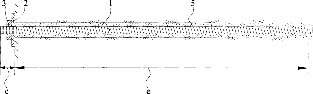
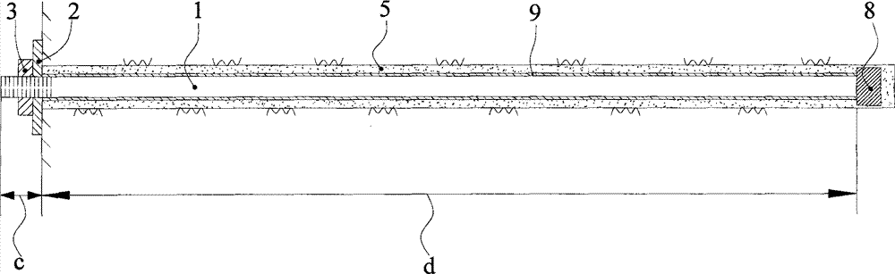
[0041] figure 1 and figure 2 They are respectively the schematic diagrams of the existing tension type anchor rod and the pressure type anchor rod, and their structures will not be described in detail.

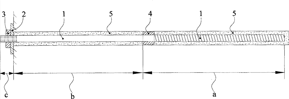
[0042] Combine below Figure 3-Figure 7 The technical solution of the present invention is described.

[0043] Such as image 3 As shown, a tension-compression coupling type high-strength deformation anchor is mainly composed of an anchor body 1, a tray 2 and a nut 3, and the nut 3 outside the hole is used as the outer anchoring section c after being tightened, and the anchoring agent 5 is poured into the hole and then combined with The anchor body 1 is bonded as the inner anchoring section; the surface of the anchor body 1 of the inner anchoring section is in two states, the section near the hole is smooth and round, and the section near the bottom of the hole is rough; smooth and round The rod body constitutes a temporary inner anchoring section b, also known as "quasi-...


PUM


Abstract

The invention discloses a tension and compression coupling type high-strength and high-deformation anchor rod and a method for using the same. The tension and compression coupling type high-strength and high-deformation anchor rod mainly consists of an anchor rod body, a tray and a nut, the outside of a hole is fixed by the nut and is used as an outer anchoring section, the inside of the hole is adhered with the anchor rod body after being filled with anchoring agents and is used as an inner anchoring section, the surface of the anchor rod body of the inner anchoring section is in two states, a portion, which is close to a hole opening, of the surface of the anchor rod body of the inner anchoring section is smooth and round, a portion, which is close to a hole bottom, of the surface of the anchor rod body of the inner anchoring section is rough, the smooth and round rod body is a temporary inner anchoring section, namely a quasi-free section, the rough rod body is a permanent inner anchoring section, and a load bearing table is arranged on the rod body and is adjacent to the permanent inner anchoring section and the temporary inner anchoring section. The stress state of the anchor rod during field application is obviously optimized, the tension and compression coupling type high-strength and high-deformation anchor rod is simple in structure, and the reliability and the supporting effect of the anchor rod are improved obviously under the conditions that construction efficiency is not affected and cost is only increased a little.

Description

technical field [0001] The invention relates to a support bolt used in projects such as water conservancy and hydropower, slopes, tunnels and mines, in particular to a high-strength prestressed deformable bolt and a method for using the same. Background technique [0002] In the engineering support process of mines, water conservancy and hydropower, slopes and tunnels, bolts are a kind of support equipment that is widely used. With the continuous increase of mining depth and the construction of large-scale underground projects, the geological conditions are becoming more and more complex, and the surrounding rock often shows the characteristics of high stress and large deformation. This situation requires the anchor rod to have both high anchoring force and good deformation performance. [0003] According to the stress state of the grouting body, anchors can be divided into two types, one is tension anchors and the other is pressure anchors. [0004] Tensile anchors such a...

Claims


Application Information

Patent Timeline
Patent Type & Authority Patents(China)
IPC IPC(8): E21D21/00E02D5/74
Inventor 王刚吴学震蒋宇静
Owner SHANDONG UNIV OF SCI & TECH
Why Eureka
Try Eureka