
Clean room

A technology of clean room and fan, which is applied in the field of clean room, can solve the problem that the dust particles in the clean room are not easy to be discharged, and achieve the effect of reducing eddy current phenomenon and improving product yield

Active Publication Date: 2015-01-07
TCL CHINA STAR OPTOELECTRONICS TECH CO LTD
View PDF5 Cites 0 Cited by
  • Summary
  • Abstract
  • Description
  • Claims
  • Application Information

AI Technical Summary

Problems solved by technology

[0005] The technical problem mainly solved by the present invention is to provide a clean room to solve the problem in the prior art that the dust particles in the clean room are not easily discharged due to the eddy current phenomenon.

Method used


Image

  • Clean room
  • Clean room
  • Clean room

Examples


Embodiment Construction

[0036] The following will clearly and completely describe the technical solutions in the embodiments of the present invention with reference to the accompanying drawings in the embodiments of the present invention. Obviously, the described embodiments are only some, not all, embodiments of the present invention. Based on the embodiments of the present invention, all other embodiments obtained by persons of ordinary skill in the art without making creative efforts belong to the protection scope of the present invention.

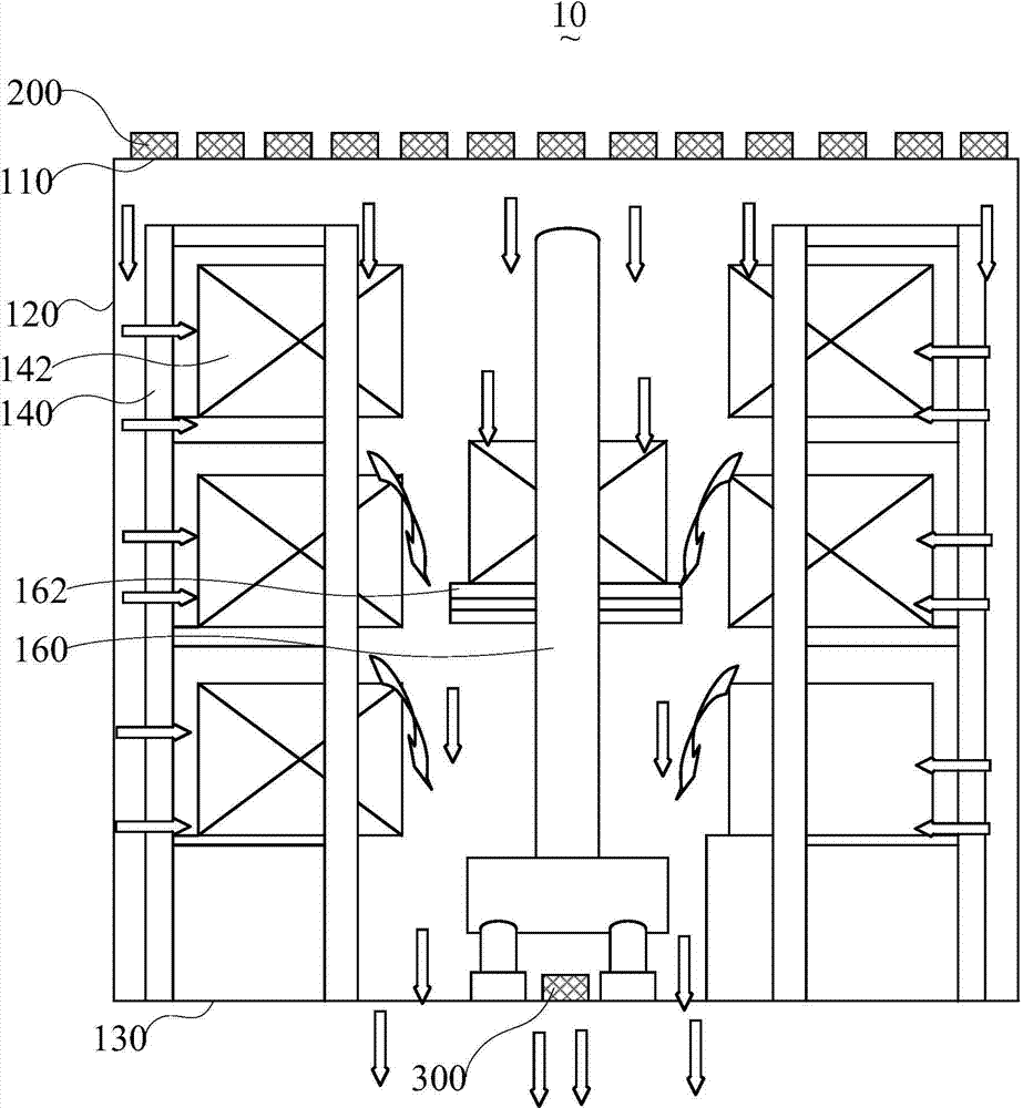
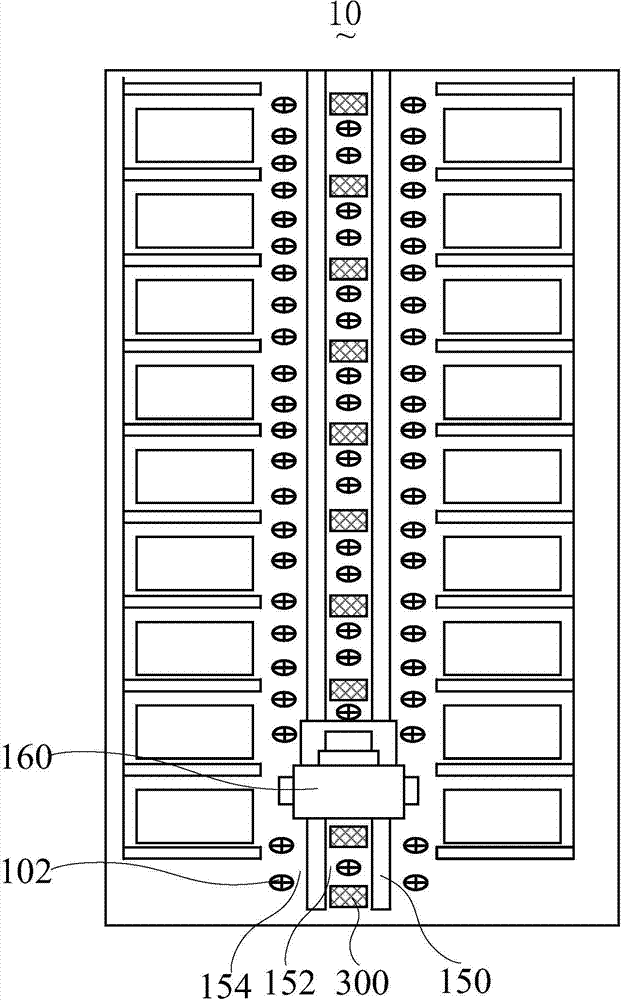
[0037] Please also refer to figure 1 and figure 2 ,in, figure 1 It is a front view cross-sectional schematic diagram of a clean room according to a preferred embodiment of the present invention; figure 2 It is a top cross-sectional schematic diagram of a clean room according to a preferred embodiment of the present invention.

[0038] Such as figure 1 and figure 2 As shown, the present invention provides a clean room 10 for storing glass substrates. Th...


PUM


Abstract

A clean room (10) for use in storing glass substrates. The clean room comprises a ventilation outlet (102), a first fan filter unit (200), and a second fan filter unit (300). The ventilation outlet (102) is arranged at the bottom part of the clean room. The first fan filter unit (200) is arranged at the top part of the clean room and is used to provide the clean room with clean air. The second fan filter unit (300) is arranged at the bottom part of the clean room and is used in tandem with the first fan filter unit (200) to form a vertical airflow, thereby reducing a vortex phenomenon in the clean room. The clean room solves the problem in the prior art that dust particles in the clean room are difficult to be discharged due to the vortex phenomenon.

Description

technical field [0001] The invention relates to the technical field of liquid crystal panel production, in particular to a clean room. Background technique [0002] Clean room is also called clean room or clean room. The main function of clean room is to control the cleanliness, temperature and humidity of the air in contact with products (such as glass substrates), so that products can be produced and manufactured in a good environment. . [0003] In the prior art, the cleaning of the clean room is to blow clean air into the clean room through the fan filter unit on the top plate of the clean room, and discharge the polluted air (including dust particles, etc.) in the clean room from the air outlet. [0004] However, in the actual process, when the fan filter unit on the top plate of the clean room blows clean air into the clean room, it is easily affected by the eddy current phenomenon caused by the automatic handling equipment in the clean room, the bottom plate of the c...

Claims


Application Information

Patent Timeline
Patent Type & Authority Patents(China)
IPC IPC(8): F24F7/007F24F13/28E04H5/02
CPCB65G2249/02F24F3/161B65G49/068F24F3/167
Inventor 蒋运芍吴俊豪林昆贤汪永强舒志优郭振华
Owner TCL CHINA STAR OPTOELECTRONICS TECH CO LTD
Learn More