Torque sensor

A torque sensor and stress technology, applied in the field of test measurement, can solve problems such as the inability to guarantee the measurement accuracy and the inability to measure the torque of the object to be measured, and achieve the effect of eliminating the influence

Inactive Publication Date: 2013-01-09
NORTHWESTERN POLYTECHNICAL UNIV
View PDF6 Cites 9 Cited by
  • Summary
  • Abstract
  • Description
  • Claims
  • Application Information

AI Technical Summary

Problems solved by technology

[0004] The problem to be solved by the present invention is: when the torque of the drive shaft is measured by means of a clamp ring to obtain the torque of the object to be measured, the measurement accuracy cannot be guaranteed and the torque of the object to be measured cannot be measured at rest. Therefore, the present invention proposes a torque sensor

Method used


Image

  • Torque sensor
  • Torque sensor
  • Torque sensor

Examples


Embodiment Construction

[0014] Describe the present invention below in conjunction with specific embodiment:

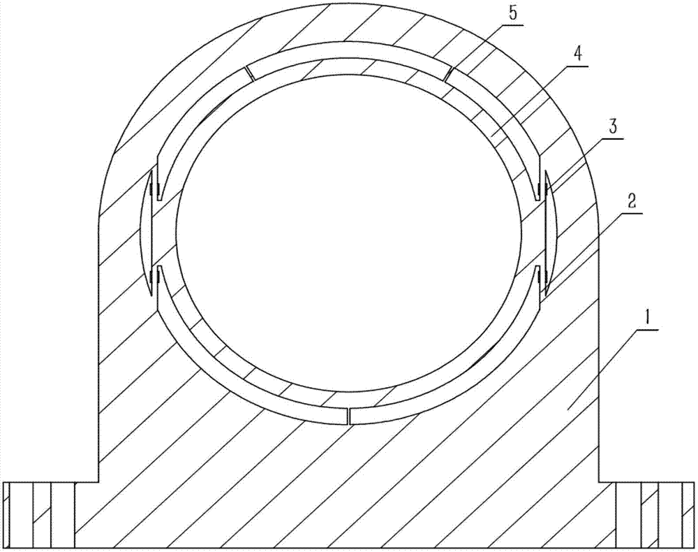
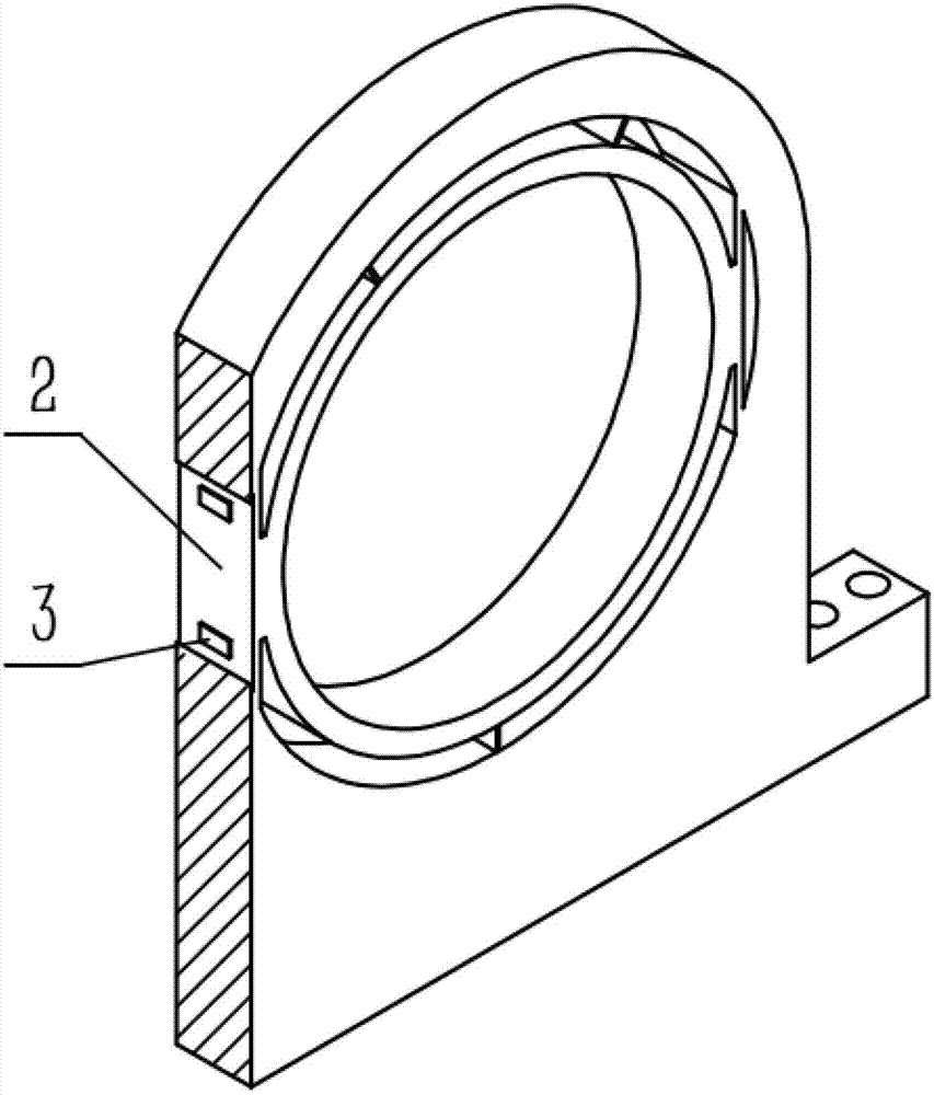
[0015] The torque sensor in this embodiment is composed of a support seat 1 , a stress plate 2 , a sleeve 4 , a thin-walled plate 5 and a resistance strain gauge 3 .

[0016] Refer to attached figure 1 , The support seat 1, the stress plate 2 and the sleeve 4 are integrally formed structures. The sleeve 4 is coaxially and fixedly connected with the support seat 1 through the stress plates 2 tangentially on both sides. In this embodiment, the stress plate 2 is vertically located at the left and right ends of the sleeve 4, and connects the sleeve 4 and the supporting seat 1 together. The stress plates on both sides are symmetrical with respect to the central axis of the sleeve, and the outer surfaces of the stress plates on both sides are tangential planes to the edge of the sleeve. The thickness of the stress plates is between 2 mm and 5 mm to ensure the accuracy of measurement. In this emb...


PUM

PropertyMeasurementUnit
thicknessaaaaaaaaaa
thicknessaaaaaaaaaa

Abstract

The invention provides a torque sensor which is composed of a supporting base, stress plates, a sleeve, a thin-wall plate and resistance strain gages. The supporting base, the stress plates and the sleeve are an integrated forming structure, the sleeve is coaxially and fixedly connected with the supporting base through the tangential stress plates on two sides, the stress plates on the two sides are symmetrical with the central axis of the sleeve as the center, the outer surfaces of the stress plates on the two sides serve as tangential planes of the edges of the sleeve, and the thickness of the stress plates is between 2mm to 5mm. The resistance strain gages are attached to the inner sides and the outer sides of the stress plates, the resistance strain gages on the stress plate on one side are distributed symmetrically with the center of the stress plate as the center, and the thin-wall plate along the normal direction of the sleeve is connected between the sleeve and the supporting base. The torque sensor can be used for measuring torque of a transmission shaft directly and does not need to dismantle a measuring device, the resistance strain gages symmetrically arranged on two sides of the stress plates can eliminate influence of temperature on measuring results, and torque of an object to be measured under the static condition can be measured.

Description

technical field [0001] The invention relates to the technical field of test measurement, in particular to a torque sensor, which measures torque according to the measurement principle of resistance strain gauges. Background technique [0002] A Chinese invention patent with publication number CN1752725A discloses a clamp-ring type torque sensor for acquiring a torque signal of a drive shaft. The sensor adopts a semi-ring design, and only bolts / nuts are needed to quickly clamp the sensor to the transmission shaft. When the transmission bearing is subjected to torque, the shear deformation on the transmission shaft proportional to the torque is transmitted to the sensor elastic body , paste the resistance strain gauge on the elastic body of the sensor, so as to obtain the torque signal of the transmission shaft. However, the sensor obtains the torque of the object to be measured by measuring the torque of the drive shaft through a clamp ring. The measuring device needs to be ...

Claims


Application Information

Patent Timeline
Patent Type & Authority Applications(China)
IPC IPC(8): G01L3/02
Inventor 张贤杰王俊彪王兵曹小宝司朝润
Owner NORTHWESTERN POLYTECHNICAL UNIV
Why Eureka
Try Eureka