Pull type direct pulling device

A lifting and straight-pulling technology, which is applied in the direction of measuring devices, instruments, scientific instruments, etc., can solve the problems of concrete core samples slipping and falling off, concrete core samples being crushed, etc., and achieve the effect of reducing the weight of the device and being easy to use

Active Publication Date: 2013-01-09
CABR TECH CO LTD
View PDF5 Cites 10 Cited by
  • Summary
  • Abstract
  • Description
  • Claims
  • Application Information

AI Technical Summary

Problems solved by technology

[0005] The purpose of the present invention is to provide a dynamic pulling-type straight-pulling device in which the holding force will also increase with the increase of the pulling force. The technical problem of crushing the concrete core sample or making the concrete core sample slip off from the mechanical straight puller

Method used


Image

  • Pull type direct pulling device
  • Pull type direct pulling device
  • Pull type direct pulling device

Examples


Embodiment Construction

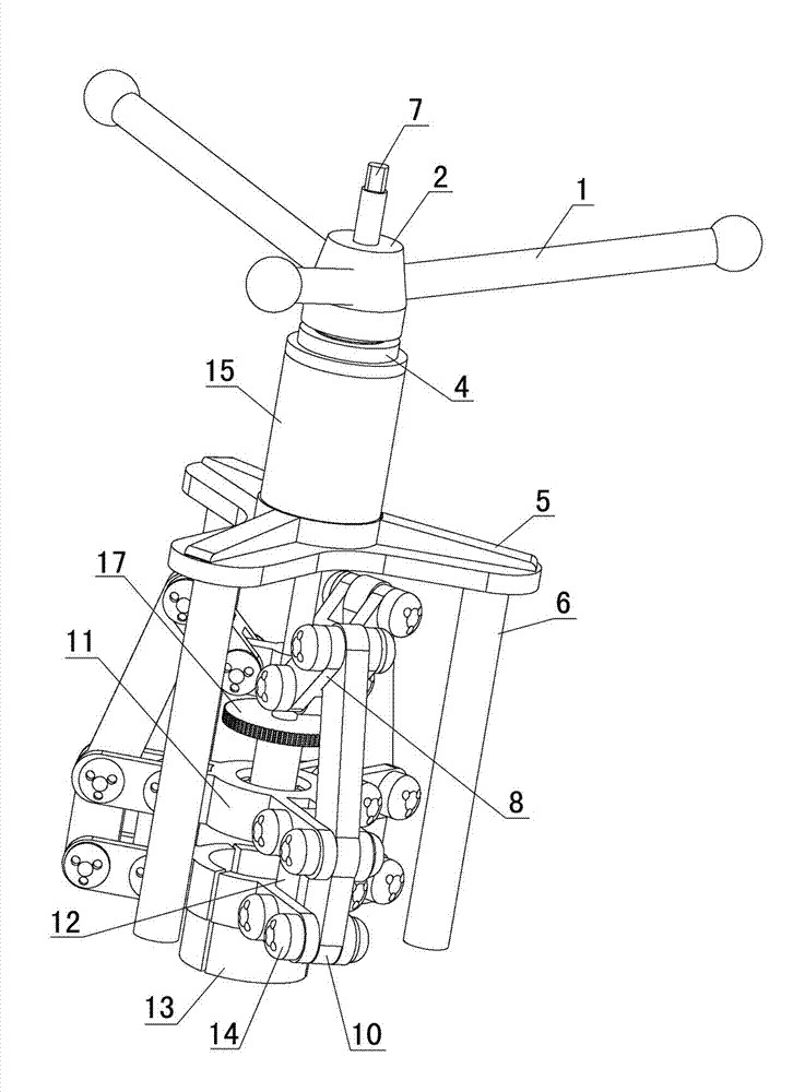
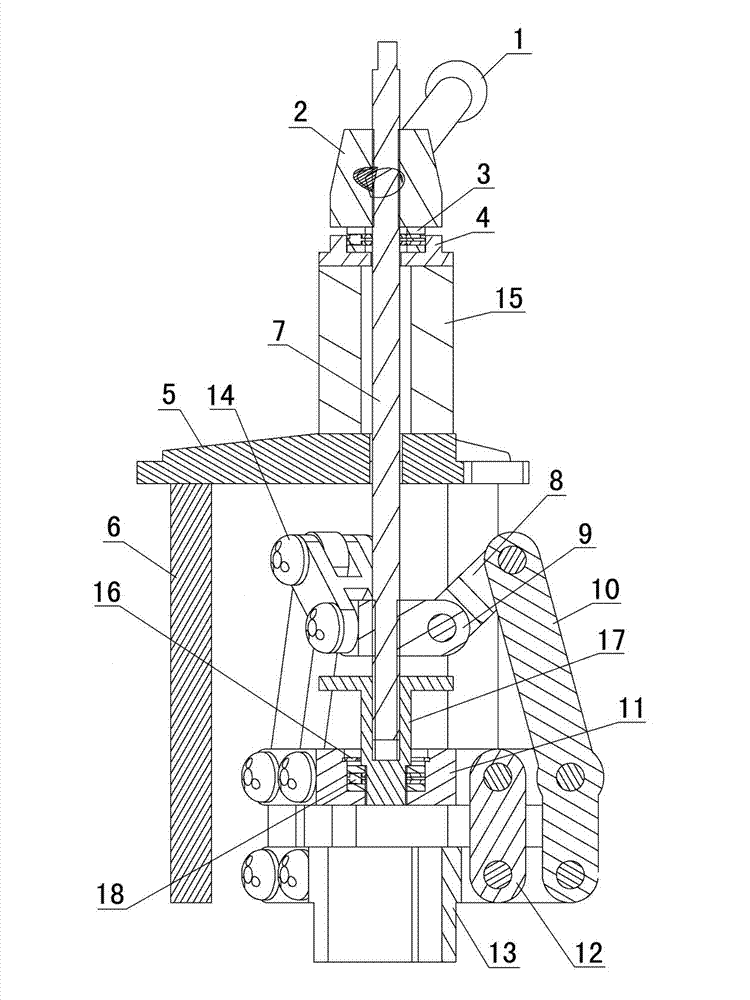
[0038] Examples see Figure 1-7As shown, this lifting type straight pulling device is composed of four parts: a straight pulling head, a reaction force frame, a pressure sensor 15 and a force application mechanism. Pulling the head, the reaction force frame, the pressure sensor 15 and the force applying mechanism are sequentially sleeved on the lifting rod 7 above the pulling head from bottom to top, and the force applying mechanism is also threaded with the lifting rod 7 . The lifting rod 7 between the pressure sensor 18 and the force applying mechanism is covered with a bearing seat 4 and a second bearing 3, and the function of the bearing seat 4 and the second bearing 3 is to reduce the friction between the force applying mechanism and the pressure sensor force.

[0039] The reaction force frame is composed of a support frame seat 5 sleeved on the lifting rod 7 and at least three support rods 6 fixedly connected to the lower surface of the support frame seat 5 .

[0040] ...


PUM

PropertyMeasurementUnit
depthaaaaaaaaaa

Abstract

The invention relates to a pull type direct pulling device which comprises a direct pulling head, a reaction rack, a pressure sensor and a stress application mechanism, wherein the direct pulling head comprises a pull rod and a pull head connected with the lower part of the pull rod; the pull head comprises a hoist block, a jacking thread sleeve, a fixed plate, claws and a link mechanism, the hoist block is in threaded connection with the pull rod, the jacking thread sleeve is in threaded connection with the pull rod under the hoist block, the fixed plate is sheathed outside the jacking thread sleeve through a first bearing bush, the fixed plate is uniformly provided with at least three fixed plate connecting rods, the claws are positioned under the fixed plate, and the number of the claws is the same as the number of the fixed plate connecting rods. The fastening force is enhanced along with the enhancement of the pull force when a concrete core sample is pulled by the pull type direct pulling device, so that the situations that the concrete core sample is smashed by clamping, or is slipped out and fall off from a mechanical direct pull head cannot happen. The pull type direct pulling device is formed by adopting rods, the weight of the pull type direct pulling device can be reduced, and the pull type direct pulling device is more convenient to use.

Description

technical field [0001] The invention relates to the technical field of detecting concrete strength by a direct pulling method, in particular to a direct pulling device (also called a pulling device). Background technique [0002] The original direct pull method to test the strength of concrete is bonding direct pull, that is, drill a concrete core sample (generally ??38mm,?? or 49mm), dry it with a hair dryer, then use an adhesive (usually epoxy resin) to bond the bowl-shaped drawing head with the concrete core sample, and then connect the bowl-shaped drawing head to the straight-drawing device , the direct pulling device pulls out the concrete core sample under the action of the reaction force frame, and measures the pulling strength at the same time, and finally infers the concrete compressive strength of the concrete component to be tested according to the measured pulling strength. [0003] Although bonding and direct pulling has many advantages, there are still the fol...

Claims


Application Information

Patent Timeline
Patent Type & Authority Applications(China)
IPC IPC(8): G01N3/02
Inventor 朱跃武邱平朱丽颖李新喜朱俊峰石永
Owner CABR TECH CO LTD
Why Eureka
Try Eureka