Continuous pressurizing device

A pressure device, piezoelectric ceramic technology, used in measuring devices, using stable tension/pressure to test the strength of materials, instruments, etc. problem, to achieve the effect of increasing hydrostatic pressure and high pressure output accuracy

Inactive Publication Date: 2014-07-30
INST OF SEMICONDUCTORS - CHINESE ACAD OF SCI
View PDF4 Cites 0 Cited by
  • Summary
  • Abstract
  • Description
  • Claims
  • Application Information

AI Technical Summary

Problems solved by technology

[0003] However, when the diamond anvil is used for low-temperature hydrostatic pressure experiments, since the anvil device is fixed in the cryostat, each pressurization needs to be realized by tightening the screws on the anvil with a screwdriver at room temperature , instead of applying pressure while doing low temperature experiments
Moreover, the previous pressurization methods cannot accurately control the size of the pressurized pressure, and can only be estimated by experience.
These have a large effect on the experiment, making hydrostatic experiments very tedious and with large uncertainties

Method used


Image

  • Continuous pressurizing device
  • Continuous pressurizing device

Examples


Embodiment Construction

[0018] In order to make the object, technical solution and advantages of the present invention clearer, the present invention will be described in further detail below in conjunction with specific embodiments and with reference to the accompanying drawings.

[0019] It should be noted that, in the drawings or descriptions of the specification, similar or identical parts all use the same figure numbers. Implementations not shown or described in the accompanying drawings are forms known to those of ordinary skill in the art. Additionally, while illustrations of parameters including particular values ​​may be provided herein, it should be understood that the parameters need not be exactly equal to the corresponding values, but rather may approximate the corresponding values ​​within acceptable error margins or design constraints. In addition, the directional terms mentioned in the following embodiments, such as "upper", "lower", "front", "rear", "left", "right", etc., are only re...


PUM


Abstract

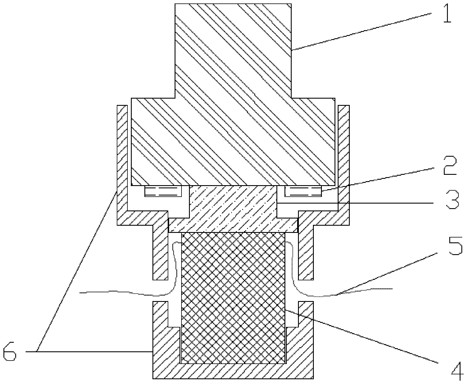
The invention provides a continuous pressurizing device. The continuous pressurizing device comprises a barrel (6), piezoelectric ceramics (4) which is arranged inside the barrel (6), a slide block (3) which is arranged inside the barrel (6) and pressed on the upper surface of the piezoelectric ceramics (4) and a counter-jacking anvil (1), wherein the outer side wall of the slide block slides up and down along the inner side wall of the barrel (6); and a part of the counter-jacking anvil (1) is arranged inside the barrel (6) and pressed on the upper surface of the slide block (3). The continuous pressurizing device can continuously and precisely pressurize a sample to be tested.

Description

technical field [0001] The invention relates to fluid static pressure technology, in particular to a continuous pressurizing device which can continuously and accurately apply fluid static pressure in a cryostat. Background technique [0002] As an effective experimental method for studying semiconductor materials, hydrostatic pressure technology is widely used in the research fields of optical properties, electrical properties, and phase transitions of semiconductors. Applying hydrostatic pressure requires a diamond-to-anvil arrangement. The principle of the diamond counter-anvil device is to place the sample in a pressure chamber formed by two opposite diamonds and spacers whose upper and lower anvil surfaces are parallel, fill the pressure chamber with a pressure transmission medium, and push the two diamonds to make them mutually When extruding, through the pressure transmission medium, hydrostatic pressure will be generated on the sample. The diamond anvil technology ...

Claims


Application Information

Patent Timeline
Patent Type & Authority Patents(China)
IPC IPC(8): G01N3/18G01N3/02
Inventor 武雪飞丁琨窦秀明孙宝权
Owner INST OF SEMICONDUCTORS - CHINESE ACAD OF SCI
Why Eureka
Try Eureka