Detection system and detection method for power terminal

A detection system and detection method technology, applied in the direction of electronic circuit testing, measuring electricity, measuring devices, etc., can solve problems such as being unsuitable for mass production and testing processes, many terminal leads, and low operating efficiency, and improve production testing. Efficiency, saving operation time, saving the effect of manufacturing cost

Inactive Publication Date: 2013-01-09
安徽中鑫继远信息技术股份有限公司
View PDF4 Cites 26 Cited by
  • Summary
  • Abstract
  • Description
  • Claims
  • Application Information

AI Technical Summary

Problems solved by technology

[0002] At present, most of the detection of power terminals adopts the manual detection method. There are many terminals and terminal leads. Mass production and testing process

Method used


Image

  • Detection system and detection method for power terminal

Examples


Embodiment 1

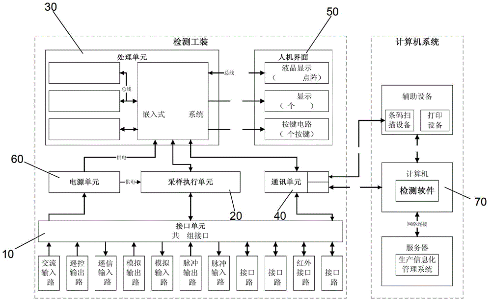
[0020] combine figure 1 , the concrete constitution of the present invention is as follows:

[0021] A detection system for a power terminal, the detection system includes an interface unit 10, a sampling execution unit 20, a processing unit 30, a communication unit 40, a power supply unit 50, a man-machine interface 60 and detection software 70:

[0022] (a) The quick connection between the interface unit 10 and the terminal equipment under test consists of six parts: a base, a sliding seat, a rocker, an operation panel, a probe, and a connecting line;

[0023] (b) The sampling execution unit 20 is connected to the terminal under test through the probe of the interface unit 10, converts the analog signal of the terminal under test into a digital signal for identification by the processing unit, and converts the digital signal preset by the processing unit 30 into an analog signal for the terminal to be tested Test terminal identification; the unit is composed of AD, DA conve...

Embodiment 2

[0033] A detection method of the system according to claim 1, wherein the detection system automatically reads the configuration file of the terminal when starting the test, obtains the basic information of the terminal under test therefrom, and stores it in the test report; after the detection is completed, Automatically complete the recording function of basic information, testing information, testing data and testing results, and has the function of exporting and saving the above information.

[0034] The detection software of the test system consists of four parts: basic information, detection information, detection data and detection results, among which:

[0035] (a) Basic information: set by the configuration file of the testing tool, including terminal name, terminal model, terminal version, hardware version, software version, terminal number, inspector, testing date, etc.;

[0036] (b) Detection information: intuitively reflects the information of the tested terminal,...


PUM


Abstract

The invention relates to a detection system for a power terminal, wherein the detection system can improve the protection test efficiency by being used for automatically detecting power terminal input equipment, power terminal output equipment, interfaces and functions, being used for automatically generating a test report, being connected with a production informatization management system by detection software, and being used for outputting the test report or uploading the test report to the production informatization management system. The detection system comprises an interface unit, a sampling execution unit, a processing unit, a communication unit, a human-computer interface, a power supply unit and detection software. The operation of manual and repeated wiring can be omitted, the operation time can be saved, the production detection efficiency of the power terminal can be improved, the manufacture cost can be saved, and the informatization management function of a production and detection process can be realized.

Description

technical field [0001] The invention relates to the fields of design verification, production, detection and application of electric power terminals, specifically a detection system for electric power terminals. Background technique [0002] At present, most of the detection of power terminals adopts the manual detection method. There are many terminals and terminal leads. Mass production and testing process. Contents of the invention [0003] The purpose of the present invention is to provide an automatic test for the input and output equipment, interface and function of the power terminal and automatically generate a test report, which can be connected with the production information management system through the detection software, output the test report or upload the test report To the production information management system, so as to improve the testing system of the power terminal of production testing efficiency. [0004] To achieve the above object, the present ...

Claims


Application Information

Patent Timeline
Patent Type & Authority Applications(China)
IPC IPC(8): G01R31/00G01R31/28
Inventor 徐强智建立金芝国王飞孟光李海涛
Owner 安徽中鑫继远信息技术股份有限公司
Why Eureka
Try Eureka