Radiation device and array antenna based on same

A radiation device and array antenna technology, applied in the field of array antennas, can solve problems such as the degradation of antenna transceiver performance, and achieve the effect of reducing impact and suppressing transmission

Active Publication Date: 2013-01-09
TONGYU COMM INC
View PDF6 Cites 32 Cited by
  • Summary
  • Abstract
  • Description
  • Claims
  • Application Information

AI Technical Summary

Problems solved by technology

[0004] In the existing wireless system, the antenna mainly includes a miniaturized coaxial dual-frequency or multi-frequency antenna, which adopts a common microstrip structure or a half-wave radiation device structure, and a bowl-shaped combined radiation device or a microstrip radiation device and a half-wave symmetric radiation Considering the performance of the E plane pattern of the antenna (the distance between antenna radiation devices is preferably 0.7 to 0.95 working wavelengths), therefore, when performing dual-frequency or multi-frequency antenna arrays, the distance between the high and low frequency radiation devices of the antenna The distance is small, and even the radiation arm of the low-frequency radiation device may block the high-frequency radiation device, so that two kinds of vibrators (low-frequency radiation device and high-frequency radiation device) using ordinary microstrip structure or half-wave radiation device structure There is a strong electromagnetic coupling between them, causing the radiated electromagnetic waves to be seriously interfered by the other party (low-frequency radiation device or high-frequency radiation device), that is, inter-frequency interference, which reduces the transceiver performance of the antenna

Method used


Image

  • Radiation device and array antenna based on same
  • Radiation device and array antenna based on same
  • Radiation device and array antenna based on same

Examples


Embodiment Construction

[0082] The technical solutions of the various embodiments of the present invention will be clearly and completely described below in conjunction with the accompanying drawings. Apparently, the described embodiments are only some of the embodiments of the present invention, not all of them. Based on the embodiments of the present invention, all other embodiments obtained by persons of ordinary skill in the art without making creative efforts belong to the protection scope of the present invention.

[0083] The existing coaxial dual-frequency or multi-frequency antenna adopts a common microstrip structure or a half-wave radiation device structure. When performing a dual-frequency or multi-frequency antenna array, the distance between the high and low frequency radiation devices of the array antenna is relatively small , so that strong electromagnetic coupling occurs between the low-frequency radiation device and the high-frequency radiation device, which seriously interferes with...


PUM


Abstract

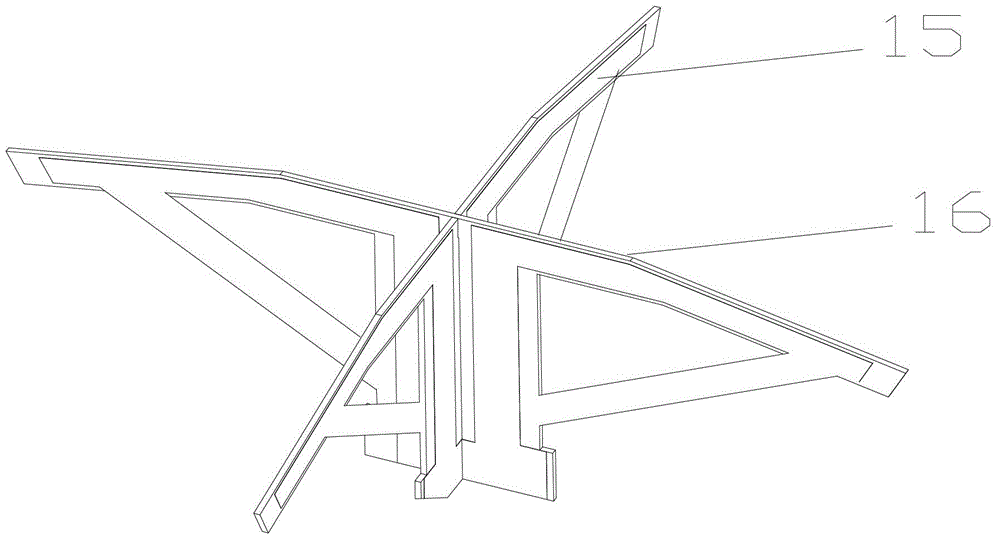
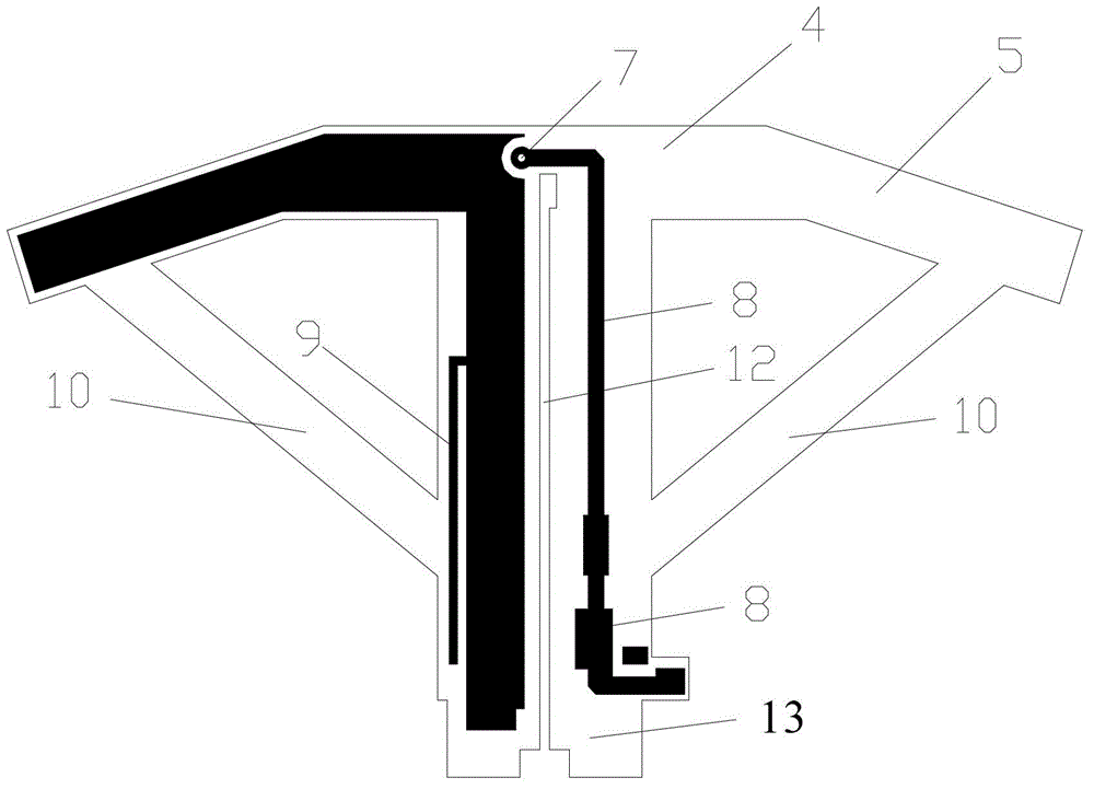
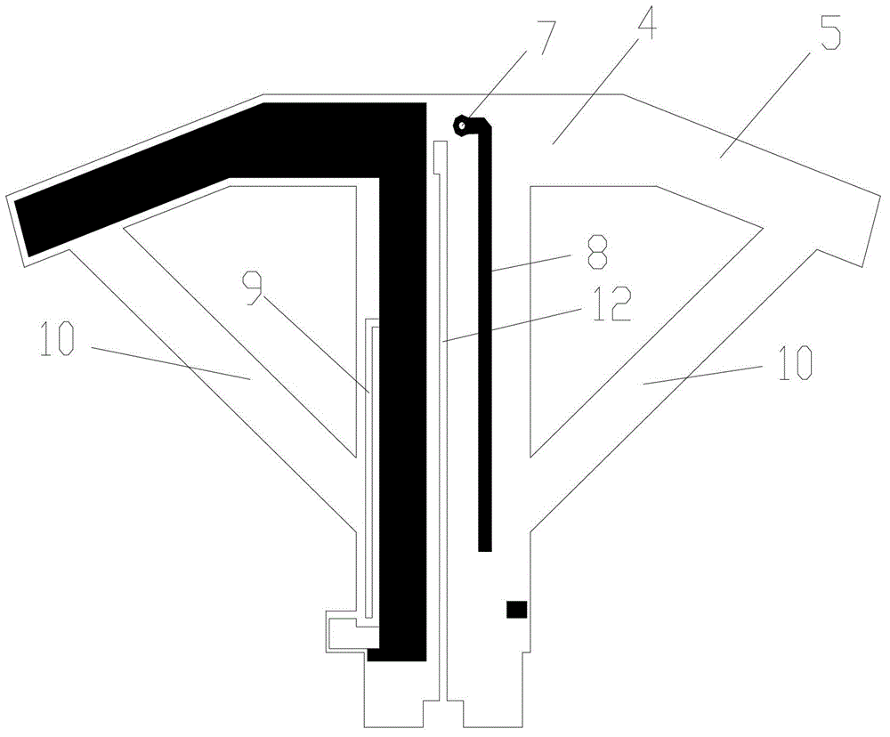
The invention discloses a radiation device and an array antenna based on the radiation device. The low-frequency radiation device comprises a first low-frequency radiation module and a second low-frequency radiation module, wherein the first low-frequency radiation module is subjected to -45-degree polarization and the second low-frequency radiation module is subjected to +45-degree polarization; the first low-frequency radiation module and the second low-frequency radiation module are symmetrically, orthogonally and fixedly connected; and open circuit branches for preventing high-frequency electromagnetic waves from being transmitted in the low-frequency radiation device are respectively arranged at one sides of the axial centers of the first low-frequency radiation module and the second low-frequency radiation module. With the adoption of the radiation device and the array antenna, the abnormal-frequency interference can be reduced and the receiving-transmitting performance of the antenna is improved.

Description

technical field [0001] The invention relates to mobile communication base station antenna technology, in particular to a radiation device and an array antenna based on the radiation device. Background technique [0002] With the advancement of high technology and economic benefits, the communication industry has become one of the largest industries in China. The rapid development of mobile communication in the communication industry makes it play an increasingly important role in the daily life of users. As of the beginning of 2010, the number of mobile communication users in my country has exceeded 736 million, and more than one million base station antennas have been put into use. , Moreover, with the continuous increase of mobile communication services and types, the working frequency bands of various mobile communication systems are also continuously expanded, resulting in the continuous increase in the volume of the antenna, the increasingly complex structure, and the hi...

Claims


Application Information

Patent Timeline
Patent Type & Authority Applications(China)
IPC IPC(8): H01Q1/36H01Q1/52H01Q21/24
Inventor 叶海欧余夙琼石磊许跃权余明江
Owner TONGYU COMM INC
Why Eureka
Try Eureka