Method and device for PUSCH (Physical Uplink Shared Channel) scheduling of terminal

A scheduling method and terminal technology, applied in the field of network communication, can solve problems such as affecting the signal transmission rate, low signal transmission rate, and inability to judge

Active Publication Date: 2014-12-24
DATANG MOBILE COMM EQUIP CO LTD
View PDF3 Cites 3 Cited by
  • Summary
  • Abstract
  • Description
  • Claims
  • Application Information

AI Technical Summary

Problems solved by technology

[0007] (1) When the uplink subframe configured with SRS is interfered, but the uplink subframe where PUSCH is located is not interfered, the CQI value measured by SRS will be lower than the actual CQI value of the uplink subframe where PUSCH is located, which will cause The initial MCS level of PUSCH scheduling is too low, resulting in low signal transmission rate
[0008] (2) When the uplink subframe configured by SRS does not receive interference, but the uplink subframe where PUSCH is located is interfered, the CQI value measured by SRS will be higher than the actual CQI of the uplink subframe where PUSCH is located, which will cause PUSCH scheduling The initial MCS level is too high, resulting in too high a block error rate (BLock Error Rate, BLER)
[0009] (3) When PUSCH is transmitted in multiple uplink subframes and the interference is inconsistent, the uplink subframe with large interference will lower the overall MCS level, so that the MCS used for the transmission of the uplink subframe with small interference is too low , so that the transmission rate of the signal is too low
[0010] To sum up, the current method of determining the MCS level of the PUSCH of the terminal cannot accurately judge the uplink subframe without SRS configuration, which affects the signal transmission rate and the bit error rate is high

Method used


Image

  • Method and device for PUSCH (Physical Uplink Shared Channel) scheduling of terminal
  • Method and device for PUSCH (Physical Uplink Shared Channel) scheduling of terminal
  • Method and device for PUSCH (Physical Uplink Shared Channel) scheduling of terminal

Examples


Embodiment Construction

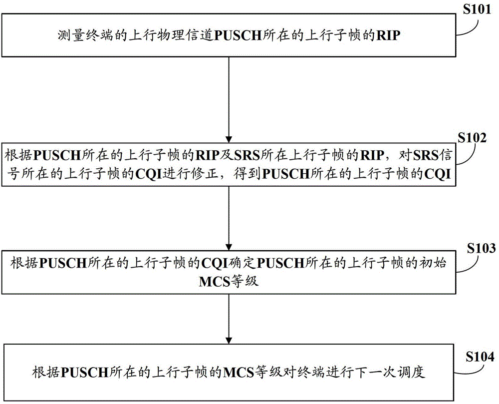
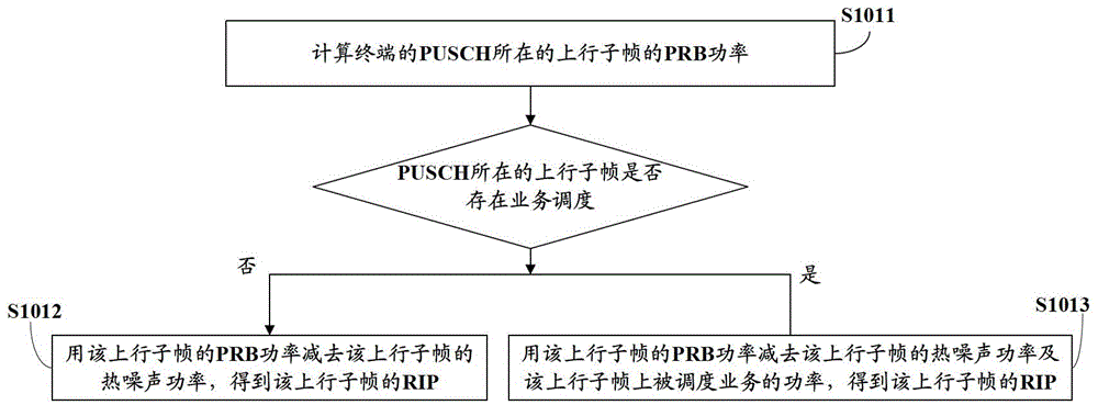
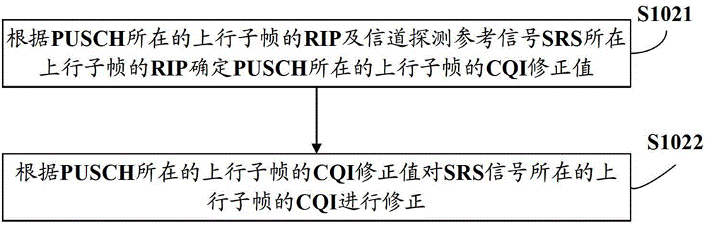
[0029] Embodiments of the present invention provide a PUSCH scheduling method and device for a terminal. According to the RIP of the uplink subframe where the PUSCH of the terminal is located and the RIP of the uplink subframe where the SRS is located, the CQI of the uplink subframe where the SRS signal is located is corrected to obtain the PUSCH The CQI of the uplink subframe where the PUSCH is located, and then determine the initial MCS level of the uplink subframe where the PUSCH is located according to the CQI of the uplink subframe where the PUSCH is located, and perform next scheduling for the terminal according to the MCS level of the uplink subframe where the PUSCH is located. This technical solution takes into account the influence of different interference levels of different uplink subframes on the MCS level of scheduling PUSCH, and jointly determines the initial MCS level according to the CQI of the uplink subframe where the SRS signal is located and the actual situa...


PUM


Abstract

The embodiment of the invention provides a method and a device for PUSCH (Physical Uplink Shared Channel) scheduling of a terminal, relating to a network communication technology. The method comprises the steps of: according to the RIP (Routing Information Protocol) of an upstream subframe of the PUSCH of the terminal and the RIP of an upstream subframe of an SRS (Sounding Reference Signal), correcting a CQI (Channel Quality Indicator) of an upstream subframe of the SRS to obtain the CQI of the upstream subframe of the PUSCH, determining the grade of the initial MCS (Modulation and Coding Scheme) of the upstream subframe of the PUSCH according to the CQI of the upstream subframe of the PUSCH, and carrying out next scheduling on the terminal according to the grade of the MCS of the upstream subframe of the PUSCH. According to the technical scheme, by means of taking the influence of different interference levels of different upstream subframes to the grade of the MCS of the scheduled PUSCH into consideration and jointly determining the grade of the initial MCS according to the CQI of the upstream subframe of the SRS and the actual condition of the upstream subframe of the PUSCH, the signal transmission ratio is improved, and the error rate is reduced.

Description

technical field [0001] The present invention relates to network communication technology, in particular to a terminal PUSCH scheduling method and device. Background technique [0002] In the Time Division Long Term Evolution (TDD LTE) system of mobile communication, there are many forms of interference, including full-time full-band interference, full-time part-frequency band interference, and the most common crossover slot interference. For example, when networking, the signal transmission environment of some base stations has a water surface, which will cause the signal transmission to be far away and interfere with the signal reception of the uplink subframe of other base stations; the GPS direction of some base stations is incorrect, and the downlink signal sent will interfere with other base stations. The signal reception of the uplink subframe of the base station; there are also some base stations with the same frequency network, but when the uplink and downlink subfr...

Claims


Application Information

Patent Timeline
Patent Type & Authority Patents(China)
IPC IPC(8): H04L12/911
Inventor 倪立华李楠楠
Owner DATANG MOBILE COMM EQUIP CO LTD
Why Eureka
Try Eureka