Food waste disposer

A technology for food waste disposal and cutter head, applied in grain processing and other directions, can solve problems such as odor, failure to start the processor, and pollution of the surrounding environment.

Inactive Publication Date: 2013-01-16
LILING SHANGPIN ELECTRICAL APPLIANCE MFG
View PDF0 Cites 13 Cited by
  • Summary
  • Abstract
  • Description
  • Claims
  • Application Information

AI Technical Summary

Problems solved by technology

[0002] At present, with the continuous improvement of living standards, the amount of household waste is increasing sharply, especially the organic waste from the kitchen, such as vegetables, fruits and food waste, etc. If it is not disposed of in time, it will soon emit peculiar smell. pollute the surrounding environment
Although some households use garbage disposal machines to dispose of these organic wastes in a timely manner, most of the kitchen organic waste disposal machines currently on the market are controlled by the button of the socket connected to the processor and the button of the power state of the socket. No control device is installed to operate and control the start or stop of the processor. The garbage processor is generally installed at the bottom of the sink in the kitchen cabinet. It is very inconvenient to unplug the socket and the button control operation; It is wet, so there is a risk of electric shock for the operator during actual use. At the same time, it is easy to cause personal injury due to misoperation when starting the processor when cleaning the processor. In addition, the garbage disposal must be carried out with water, and the existing technology It is impossible to control the start of the processor by detecting whether there is water flow. In this way, it will inevitably cause the machine to be damaged by forgetting to turn on the water during operation, and sometimes the machine will rotate for a long time and be damaged when the air pressure switch is turned off when the power is suddenly cut off. phenomenon of machines etc.

Method used


Image

  • Food waste disposer
  • Food waste disposer
  • Food waste disposer

Examples


Embodiment Construction

[0017] In order to make the content of the present invention more clearly understood, the present invention will be further described in detail below based on specific embodiments and in conjunction with the accompanying drawings.

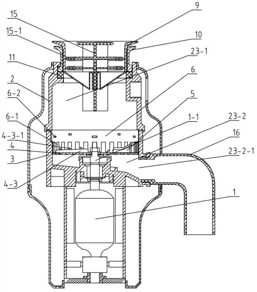
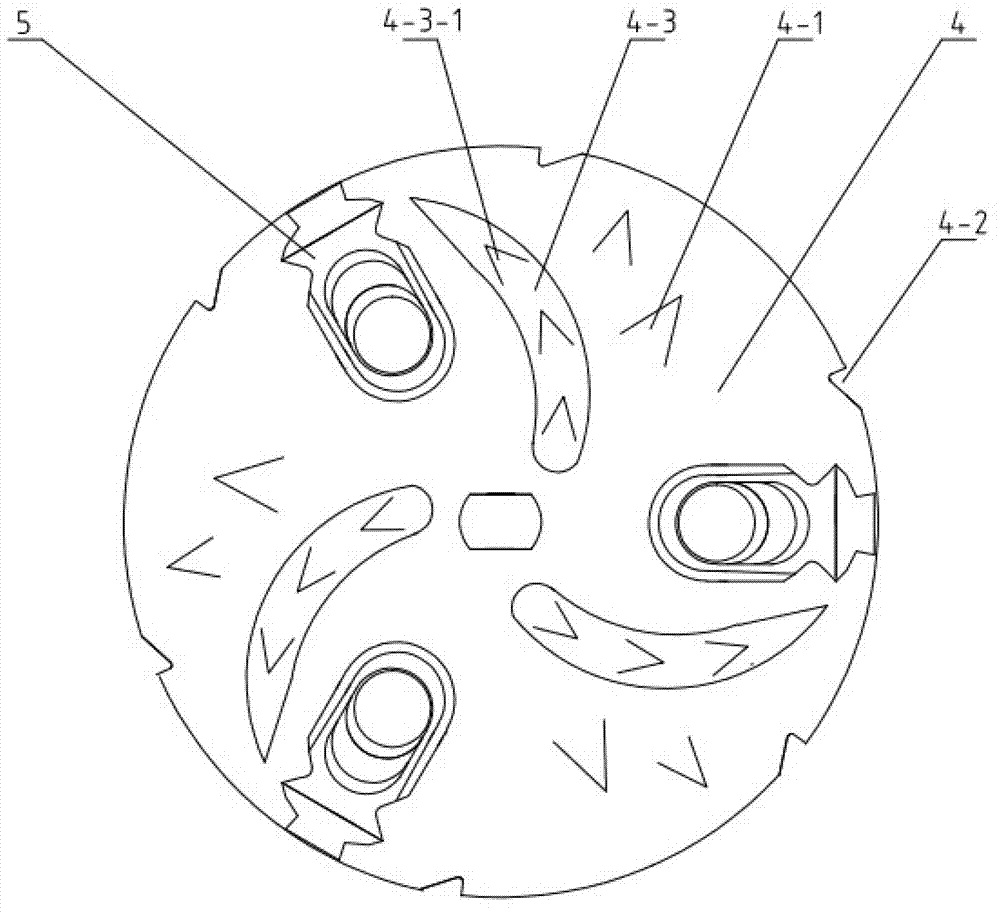
[0018] Such as Figure 1~3 As shown, a food waste disposer includes a motor 1, a grinding chamber upper shell 2 and a grinding chamber base 3 that are fixedly connected, and a cutter head 4 with a crushing knife 4-1 is arranged in the grinding chamber base 3, and the cutter head 4 is installed On the motor shaft 1-1 of the motor 1, three breaking hammers 5 are installed on the cutter head 4, and the grinding chamber upper shell 2 and the grinding chamber base 3 are provided with a grinding chamber 23-1 and a drain port 23-2-1. Blowdown chamber 23-2, grinding chamber 23-1 is positioned at the upper side of cutterhead 4, and blowdown chamber 23-2 is positioned at the lower side of cutterhead 4, and the top inner wall of grinding chamber base 3 is fix...


PUM


Abstract

The invention discloses a food waste disposer which comprises a motor, a grinding chamber upper shell and a grinding chamber base. A cutting disk with a crushing cutter is arranged in the grinding chamber base, a plurality of breaking hammers are mounted on the cutting disk, a grinding chamber and a sewage chamber with a sewage outlet are arranged in the grinding chamber upper shell and the grinding chamber base, the grinding chamber is positioned on an upper side of the cutting disk, the sewage chamber is positioned on a lower side of the cutting disk, a grinding ring is fixed on a top inner wall of the grinding chamber base, a clearance is reserved between the grinding ring and the cutting disk, and the grinding ring is provided with a plurality of grinding grooves at intervals. The food waste disposer further comprises a control device for controlling opening and closing of the motor, and the control device is connected with an air pressure switch capable of controlling connection and disconnection through an outside air pressure button and a water flow switch capable of detecting water flow of the grinding chamber. The food waste disposer is good in processing effect on high-tenacity and harder osseous waste, and can open or close a power source by detecting whether the water flow exists or not to avoid damages to the disposer.

Description

technical field [0001] The invention relates to a food waste disposer and belongs to the technical field of waste treatment equipment. Background technique [0002] At present, with the continuous improvement of living standards, the amount of household waste is increasing sharply, especially the organic waste from the kitchen, such as vegetables, melons and fruits, and food waste. Pollution to the surrounding environment. Although some households use garbage disposal machines to dispose of these organic wastes in a timely manner, most of the kitchen organic waste disposal machines currently on the market are controlled by the button of the socket connected to the processor and the button of the power state of the socket. No control device is installed to operate and control the start or stop of the processor. The garbage processor is generally installed at the bottom of the sink in the kitchen cabinet. It is very inconvenient to unplug the socket and the button control ope...

Claims


Application Information

Patent Timeline
Patent Type & Authority Applications(China)
IPC IPC(8): B02C18/12B02C13/14B02C25/00
Inventor 谢志和
Owner LILING SHANGPIN ELECTRICAL APPLIANCE MFG
Why Eureka
Try Eureka