

Polyurethane inner pipe connecting device
A connecting device and polyurethane technology, applied in the field of pipeline connecting devices, can solve the problems of cumbersome operation and complicated bonding process, and achieve the effects of ingenious technical idea, fast and firm bonding, and easy operation.
Inactive Publication Date: 2013-01-16
刘均平
View PDF5 Cites 0 Cited by
- Summary
- Abstract
- Description
- Claims
- Application Information
AI Technical Summary
Problems solved by technology
[0003] The purpose of the present invention is to provide a polyurethane inner tube connection device to solve the problems of complicated bonding process and cumbersome operation in the prior art
Method used
View moreImage
Smart ImageViewing Examples

Examples
Embodiment 2
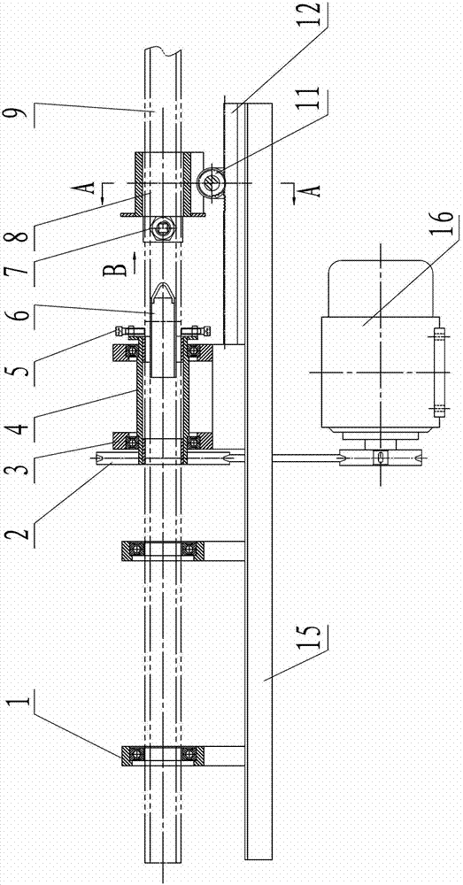
[0043] The overall structure of this embodiment is the same as that of Embodiment 1, except that the cylindrical shaft 6 adopts a hollow cylindrical structure.
Login to View More PUM
 Abstract
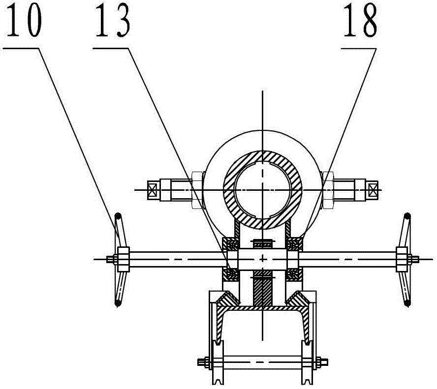
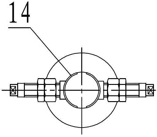
The invention belongs to a pipeline connecting device and particularly relates to a polyurethane inner pipe connecting device. The polyurethane inner pipe connecting device comprises a rotating machine head, wherein the rotating machine head is rotationally assembled on a horizontal workbench and is driven by a power source to rotate; a first clamp is arranged outside the end part on one axial side of the rotating machine head; fixed cylinder bases are distributed outside one axial side of the rotating machine head at intervals and assembled on the upper surface of the workbench; a second clamp is arranged outside one axial side of the fixed cylinder base adjacent to the rotating machine head; a linear driving mechanism, by which the fixed cylinder bases can do reciprocating motion in the axial direction, is arranged between the fixed cylinder bases and the workbench; and the fixed cylinder bases and the inner cavity of the rotating machine head are matched with a polyurethane inner pipe. The polyurethane inner pipe connecting device solves the problems that the adhesion process is complex and tedious in operation in the prior art, and has the advantages of clever structural design, simple and quick adhesion mode, workpiece positioning accuracy and reliability, operational reliability and the like.
Description
technical field [0001] The invention belongs to a pipe connection device, in particular to a polyurethane inner pipe connection device. Background technique [0002] In the invention patent application publication specification with the application number 201110166336.1, a process of bonding and connecting the inner pipe of the pouring type polyurethane feeding pipe and its special clamps are disclosed. The above-mentioned prior art mainly uses special clamps to bond the two sections into The one-piece polyurethane inner tube is fixed, and it is bonded and vulcanized by heating to fix it as a whole. The above-mentioned prior art has technical deficiencies such as complicated bonding process and cumbersome operation steps. Contents of the invention [0003] The object of the present invention is to provide a polyurethane inner pipe connection device to solve the problems of complicated bonding process and cumbersome operation in the prior art. [0004] Overall technical sc...
Claims
Login to View More Application Information
Patent Timeline
 IPC IPC(8): B29C65/52
Inventor刘均平刘玉峰刘玉丁
Owner刘均平