Spiral extrusion device

A technology of screw extrusion and extrusion cavity, which is applied in the field of screw extrusion device and solid-liquid separation equipment, and can solve the problems of exceeding the effective range of the liquid-contacting container, hidden dangers, and the safety of polluted equipment.

Inactive Publication Date: 2013-01-16
赵松桥
View PDF4 Cites 1 Cited by
  • Summary
  • Abstract
  • Description
  • Claims
  • Application Information

AI Technical Summary

Problems solved by technology

There are the following disadvantages: ①. Due to the heat generated by friction, the moisture in the liquid in the cavity will expand and splash out of the cavity along the liquid outlet tank, polluting the equipment and causing safety hazards; ②. The liquid

Method used


Image

  • Spiral extrusion device
  • Spiral extrusion device
  • Spiral extrusion device

Examples


Embodiment Construction

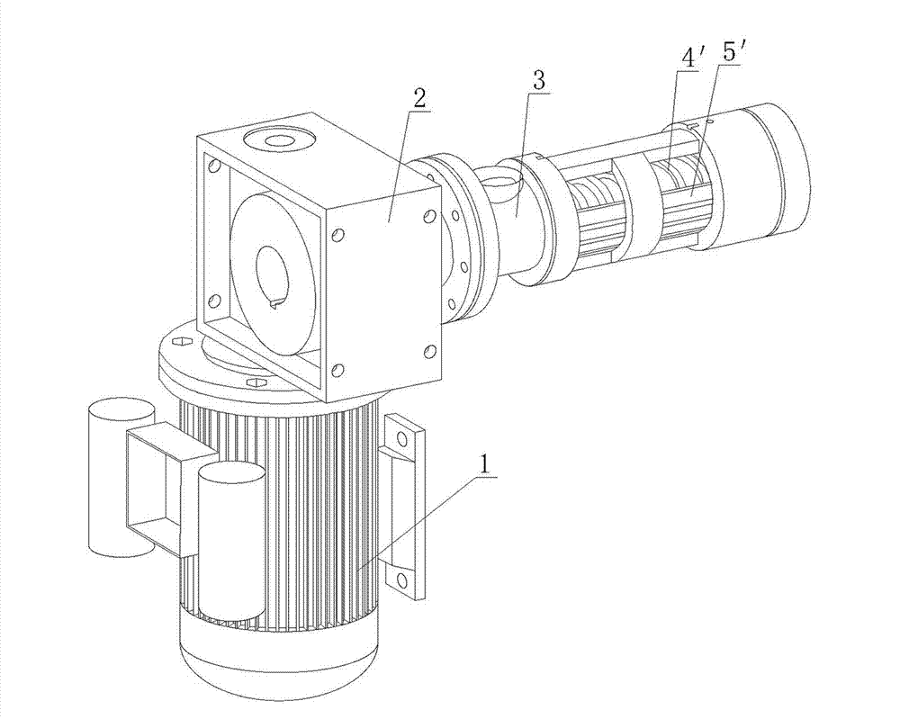
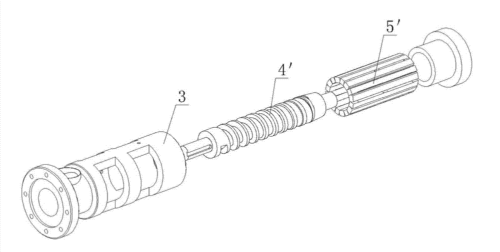
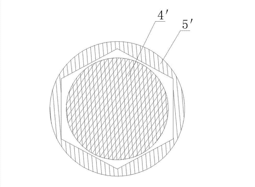
[0018] Such as Figure 4-Figure 8 As shown, the screw extrusion device of the present invention mainly includes a motor 1 and a reduction box 2, a frame body 3, an extrusion screw 4, and an extrusion chamber 5 with several extrusion grooves 51, wherein the reduction box 2 and the motor 1 connection, the extrusion screw 4 is set in the extrusion chamber 5, and the extrusion screw 4 is connected with the output shaft of the reduction box 2 and driven by the reduction box 2 to rotate in the extrusion chamber 5, each screw of the extrusion screw 4 The outer peripheral surface of the bar is processed into a polygonal structure, and the inner peripheral surface of the extrusion chamber 5 is processed into a peripheral surface structure matched with the extrusion screw 4 . Because the present invention skillfully adopts the structure combining the extruding screw rod 4 having a polygonal structure and the extruding cavity 5 having a cylindrical structure, the extrusion function of th...


PUM


Abstract

A spiral extrusion device mainly comprises a motor, a reduction box, a machine frame body, an extrusion threaded rod and an extrusion cavity with a plurality of extrusion grooves, wherein the outer circumferential surface of each spiral strip of the extrusion threaded rod is processed into a polygonal structure; and the inner circumferential surface of each extrusion cavity is processed into a circumferential surface structure matched with the extrusion threaded rod. The spiral extrusion device cleverly adopts a structure of combining the extrusion threaded rod with the polygonal structure and the extrusion cavity with the cylindrical structure, the extrusion function of the extrusion threaded rod and the extrusion cavity is realized through the coordination of the polygonal extrusion threaded rod and the cylindrical cavity, and the pressure of the extrusion cavity is alternately changed according to certain proportion to generate periodical impact force when the extrusion threaded rod rotates in the cavity at constant speed, so that a better extrusion and propulsion effect is achieved. Particularly, a polygonal structure does not need to be processed in the extrusion cavity, so the spiral extrusion device is simple in structural design and convenient to process, reduces the cost, obviously improves the production efficiency and the mounting efficiency and fulfills the aims of the invention.

Description

technical field [0001] The invention belongs to the technical field of mechanical processing, and relates to a solid-liquid separation device, in particular to a screw extrusion device for a screw extrusion juicer and an oil press. Background technique [0002] Existing screw extrusion devices such as Figure 1 ~ Figure 3 As shown, it mainly uses a cylindrical screw 4' to work in a polygonal cavity 5' (coat) to realize the extrusion function. Since the cavity is polygonal, when the screw rotates at a constant speed in the cavity, the pressure in the cavity will be according to cos¢ The ratio of :1 is alternately changed to generate periodic impact stress to achieve better extrusion and propulsion effect. Among them, due to the requirements of the production process, the dimensional accuracy of the regular polygon in the cavity is very high, which makes its processing very difficult. At present, it can only be arranged in layers. The outer layer is a cylinder, and the inner l...

Claims


Application Information

Patent Timeline
IPC IPC(8): B30B9/14
Inventor 赵松桥
Owner 赵松桥
Why Eureka
Try Eureka