
Straw briquetting machine
A molding machine and straw technology, applied in the direction of material forming presses, presses, manufacturing tools, etc., can solve the problems of difficult replacement, large vibration, complex structure, etc.
- Summary
- Abstract
- Description
- Claims
- Application Information
AI Technical Summary
Problems solved by technology
Method used
Image

Examples
Embodiment Construction
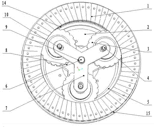
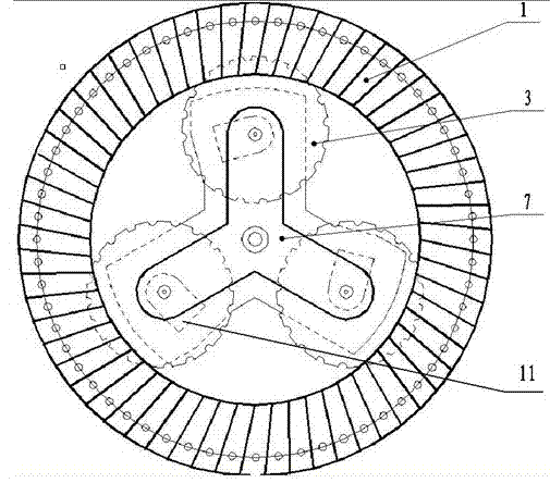
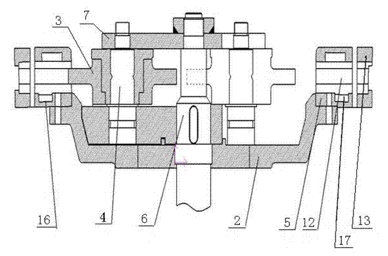
[0015] Depend on figure 1 Known, a kind of straw briquetting forming machine is provided with frame, motor, control device, main shaft barrel, extrusion die, roller, large pulley, water jacket, water tank, shaft sleeve, grinding disc, eccentric shaft and homogenizer, combination Hopper, feed pulley, discharge pulley. The central shaft 6 is driven by a large pulley, and the trident-shaped grinding disc 8 is integrally cast and fixed on the central shaft 6 through the spline 10, and rotates together with the main shaft 6, and the three eccentric shafts 4 are installed on the grinding disc 8 in equal parts. Use the key 11 and the screw to limit the position, and the gap between the roller 3 and the extrusion die 1 can be adjusted through the eccentric shaft 4. The side of the roller 3 is in the shape of semicircular teeth, and the roller 3 can rotate around the eccentric shaft 4. The upper platen 13 and the gland 5 are pressed on the grinding disc 8. The extrusion die 1 is compo...
PUM
 Abstract
Description
Claims
Application Information