High-brightness light-emitting diode (LED) panel lamp

A technology of LED panel light and LED light bar, applied in lighting device, cooling/heating device of lighting device, light source, etc., can solve the problems of affecting lighting effect, reducing light-emitting area, increasing thickness, etc., saving materials and saving The effect of production cost and weight reduction

Inactive Publication Date: 2013-01-16
BOE TECH GRP CO LTD +1
View PDF14 Cites 3 Cited by
  • Summary
  • Abstract
  • Description
  • Claims
  • Application Information

AI Technical Summary

Problems solved by technology

[0002] LED panel lights have been widely used in various industries due to their advantages of energy saving, high brightness, and no infrared and ultraviolet radiation. At present, there are two types of LED panel lights on the market; one is a direct type panel light, and the other is a side panel light. Built-in flat panel light; the structure of direct type flat panel light is: bottom reflector, LED array, diffuser plate and wide frame; if this structure is to meet large size, high brightness and uniform picture, more LED arrays and high transparency are required. If the diffuser plate has poor haze, you will see LED light shadows one by one on the light emitting surface of the panel light; this will seriously affect the lighting effect; the side-entry panel light is designed with a light guide plate , can effectively reduce the number of LED light strips, but due to the limitation of the arrangement of the LED light strips, there will be a significant difference in luminance between the light-incoming part and the light-emitting surface of the light guide plate; in addition, the above two flat panel lights are installed with external frame structure, thereby causing its light-emitting area to decrease, volume to increase, and thickness to increase; therefore, the present invention urgently needs to provide a new high-brightness LED flat panel light

Method used


Image

  • High-brightness light-emitting diode (LED) panel lamp
  • High-brightness light-emitting diode (LED) panel lamp
  • High-brightness light-emitting diode (LED) panel lamp

Examples


Embodiment 1

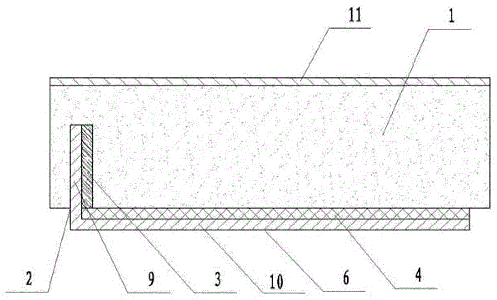
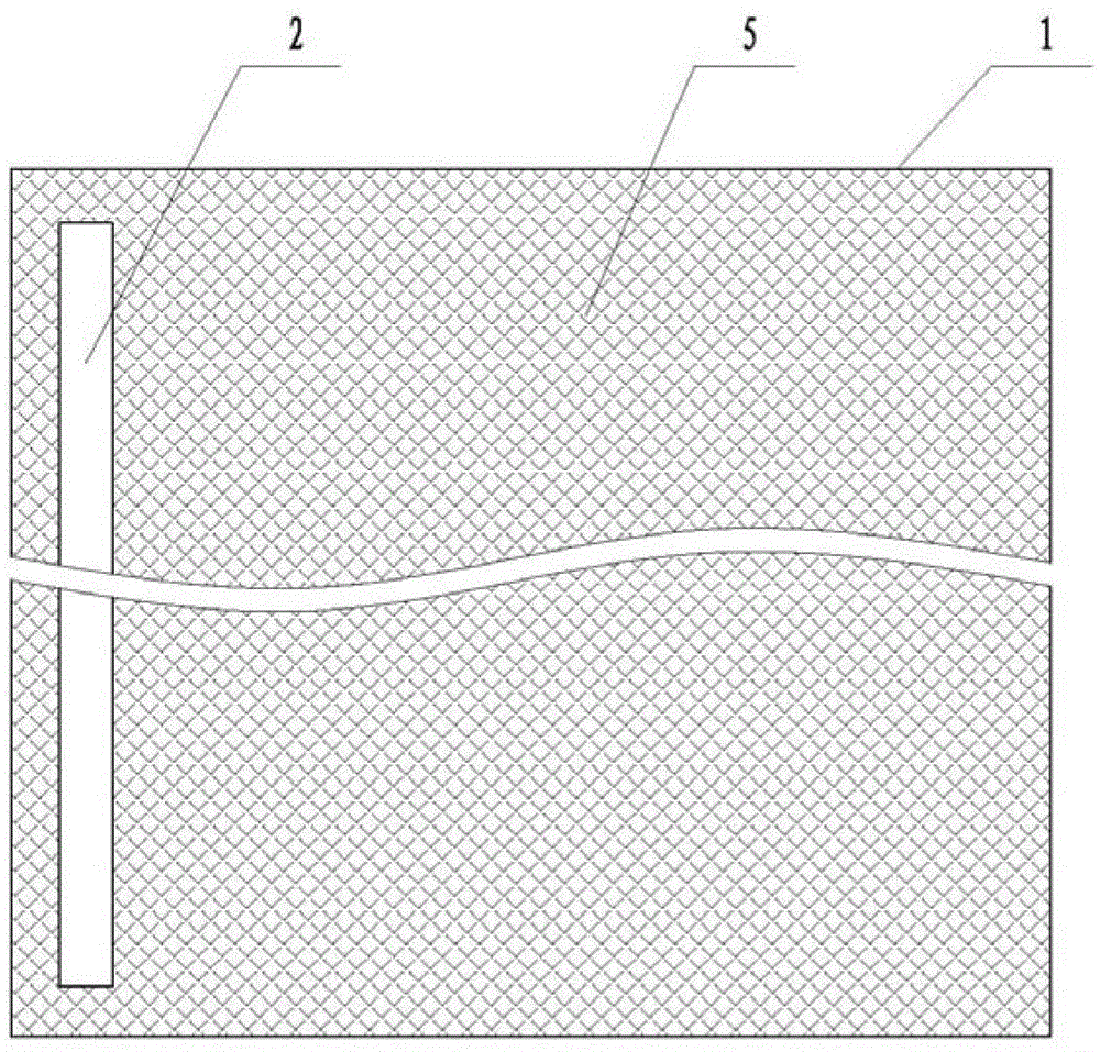
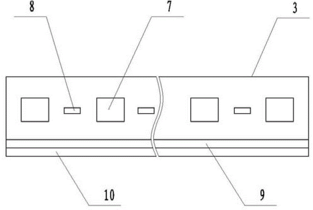
[0031] see figure 1 , figure 2 , image 3 As shown, a high-brightness LED flat panel light in this embodiment includes a light guide plate 1, a slot 2 is provided on the light guide plate, and an LED light bar 3 is arranged in the slot. The lower end of the light guide plate is provided with a reflector 4; the bayonet of the card slot is set on the left edge of the bottom surface of the light guide plate, and the card slot is vertically downward; the bottom surface of the light guide plate is arranged with dots 5; the dots are evenly distributed, and its shape It can be circular, V-shaped, rectangular, polygonal, etc. The dots are designed based on optical principles. The dots described in this embodiment are V-shaped dots formed by criss-cross rectangular arrays. The lengths of the light plates are equal, the lateral length of the rectangular array is equal to the width of the light guide plate, and the area size and dot pitch of the rectangular array can be adjusted accor...

Embodiment 2

[0037] The high-brightness LED panel light in this embodiment is an improvement on the basis of Embodiment 1. The technical content disclosed in Embodiment 1 will not be described repeatedly, and the content disclosed in Embodiment 1 also belongs to the content disclosed in this embodiment.

[0038] see Figure 4 , Figure 5 As shown, in this embodiment, in order to make the installation of the backplane and the light guide plate more firm, two card slots 101 can be provided on the light guide plate, and the bayonets of the two card slots are respectively provided on the bottom surface of the light guide plate The left and right edges of the left and right edges, the card slots are all vertically downward; a clamping plate 102 is vertically provided at the left and right ends of the pressing plate, and the LED light bar is installed on the right side wall of the left clamping plate The two clamping plates and the two card slots are correspondingly clamped; thus, the two ends ...

Embodiment 3

[0040] The high-brightness LED panel light in this embodiment is an improvement on the basis of Embodiment 1. The technical content disclosed in Embodiment 1 will not be described repeatedly, and the content disclosed in Embodiment 1 also belongs to the content disclosed in this embodiment.

[0041]see Figure 6 , Figure 7 As shown, the section of the backboard in this embodiment is shape setting; in order to improve the brightness of the flat panel lamp as a whole, two card slots are provided on the light guide plate in this embodiment; a card board is provided at both ends of the pressure plate, and the two card boards are equipped with LED light bar 201; in this embodiment, two LED light bars are connected in parallel; in order to facilitate the placement of wires for parallel connection of two LED light bars, a wiring groove 202 can be provided at the edge of the bottom surface of the light guide plate; The two ends of the wiring trough communicate with the two card sl...


PUM


Abstract

The invention relates to a high-brightness light-emitting diode (LED) panel lamp, in particular to a frameless high-brightness LED panel lamp. The panel lamp comprises a light guide plate, wherein a trough is formed on the light guide plate; an LED lamp strip is arranged in the trough; and a reflective sheet is arranged at the lower end of the light guide plate. Through the design that the LED lamp strip is arranged in the trough, an external frame is not needed, and the LED lamp strip is directly arranged in the light guide plate, so that frameless display of the panel lamp is realized, and the light-emitting area of the panel lamp is maximized; and meanwhile, the size and the thickness of the panel lamp are effectively reduced, the manufacturing cost is saved, and the production efficiency is improved.

Description

technical field [0001] The invention relates to a high-brightness LED flat panel lamp, in particular to a frameless high-brightness LED flat panel lamp. Background technique [0002] LED panel lights have been widely used in various industries due to their advantages of energy saving, high brightness, and no infrared and ultraviolet radiation. Currently, there are two types of LED panel lights on the market; Built-in flat panel light; the structure of direct type flat panel light is: bottom reflector, LED array, diffuser plate and wide frame; if this structure is to meet large size, high brightness and uniform picture, more LED arrays and high transparency are required. If the diffuser plate has poor haze, you will see individual LED light shadows on the light emitting surface of the flat panel light; this will seriously affect the lighting effect; the side-entry flat panel light is designed with a light guide plate , can effectively reduce the number of LED light strips, b...

Claims


Application Information

Patent Timeline
Patent Type & Authority Applications(China)
IPC IPC(8): F21S2/00F21V19/00F21V13/12F21V29/00F21Y101/02F21V29/503
Inventor 孟英利刘飞于志强
Owner BOE TECH GRP CO LTD
Why Eureka
Try Eureka