
Thermal infrared downlink radiation measuring device and measuring method thereof

A measuring device, thermal infrared technology, applied in electrical radiation detectors and other directions, can solve problems such as low accuracy, and achieve the effect of improving accuracy

Active Publication Date: 2015-02-25
INST OF GEOGRAPHICAL SCI & NATURAL RESOURCE RES CAS
View PDF4 Cites 0 Cited by
  • Summary
  • Abstract
  • Description
  • Claims
  • Application Information

AI Technical Summary

Problems solved by technology

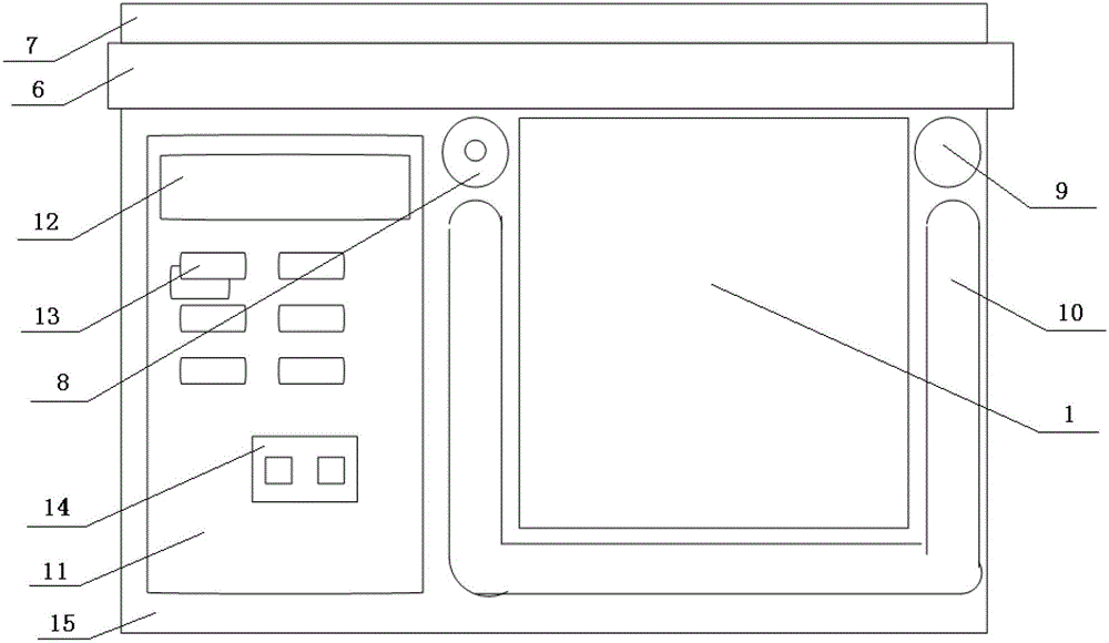
[0014] The present invention provides a thermal infrared downlink radiation measuring device and its measuring method in order to solve the problem of low accuracy in the prior art of directly measuring the temperature using a bare matte gold-plated cover plate

Method used


Image

  • Thermal infrared downlink radiation measuring device and measuring method thereof
  • Thermal infrared downlink radiation measuring device and measuring method thereof
  • Thermal infrared downlink radiation measuring device and measuring method thereof

Examples


Embodiment 1

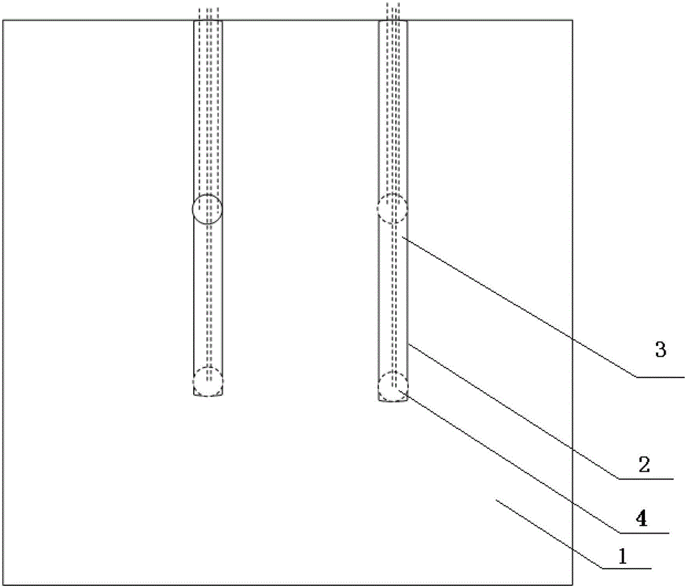
[0099] like image 3 As shown, two thermocouple placement slots 2 are distributed horizontally and at intervals, and one end of the two thermocouple placement slots 2 is respectively set at two thirds of the same side of the matte gold-plated cover plate 1, and the thermocouple placement slots The length of 2 is 2 / 3 of the side length of matt gold-plated cover plate 1;

[0100] Two thermocouple sensors 4 are arranged on each thermocouple placement groove 2 , and the two thermocouple sensors 4 are respectively arranged at the middle and end points of the thermocouple placement groove 2 .

Embodiment 2

[0102] like Figure 4 As shown, the two thermocouple placement slots 2 are horizontally dislocated and spaced apart, and one end of the two thermocouple placement slots 2 is respectively set at the trisection point of any pair of parallel sides on the matt gold-plated cover plate 1, and the thermocouple placement The length of the groove 2 is 2 / 3 of the side length of the matt gold-plated cover plate 1.

[0103] Two thermocouple sensors 4 are arranged on each thermocouple placement groove 2 , and the two thermocouple sensors 4 are respectively arranged at the middle and end points of the thermocouple placement groove 2 .

Embodiment 3

[0105] like Figure 5 As shown, the two thermocouple placement slots 2 are distributed in a cross, and the ends of the two thermocouple placement slots 2 are respectively set at the intersection of the third bisector of the matt gold-plated cover plate 1 .

[0106] Two thermocouple sensors 4 are arranged on each thermocouple placement groove 2 , and the two thermocouple sensors 4 are respectively arranged at two ends of the thermocouple placement groove 2 .

[0107] The measurement method realized by thermal infrared downlink radiation measurement device, the operation steps are as follows:

[0108] step 1,

[0109] Install the assay device in an unshielded environment.

[0110] Connect the 4 positive wires of the 4 thermocouple sensors 4 in parallel to form a positive terminal, and the 4 negative wires in parallel to form a negative terminal, and then insert them into the positive wiring hole and the negative wiring hole of the thermocouple thermometer host 11 respectively;...


PUM


Abstract

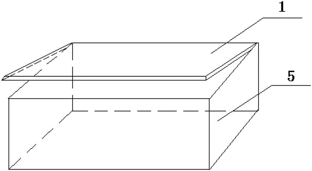
The invention provides an environmental thermal infrared irradiance measuring device and a measuring method thereof. The measuring device includes a matte gold plated cover plate, thermocouple placing grooves, thermocouple sensors, a water container, a main engine of a thermocouple temperature measuring instrument, and a thermal infrared radiometer, wherein the thermocouple placing grooves are milled and formed in the lower surface of the matte gold plated cover plate, and are provided with downward openings; the thermocouple sensors are placed in the thermocouple placing grooves; the matte gold plated cover plate is arranged at the top of the water container; the top ends of the thermocouple placing grooves are lower than the upper edge of the water container; and the thermocouple sensors are electrically connected with the thermocouple temperature measuring instrument. The measuring method includes the steps of: collecting and calculating the black-body radiation on the upper surface of the matte gold plated cover plate through thermocouples; measuring the emergent radiancy of the matte gold plated cover plate through the infrared radiometer; and obtaining the sky thermal infrared downlink radiation or the environmental thermal infrared irradiance via the conversion formula. The device is the only device for directly measuring the sky hemisphere integral downlink radiation, and the precision in temperature measurement for the outer surface of the naked matte gold plated cover plate is greatly improved.

Description

technical field [0001] The invention belongs to the field of quantitative infrared remote sensing detection, and in particular relates to a thermal infrared downlink radiation measuring device and a measuring method thereof. Background technique [0002] Thermal infrared downlink radiation is divided into the following two types, [0003] 1) Sky thermal infrared downlink radiation; [0004] The measurement device is set in an unshielded environment, and there are no tall buildings and trees around the measurement device. The thermal radiation measured in this environment is called sky thermal infrared downlink radiation. [0005] 2) Environmental irradiance; [0006] The measurement device is set in a canopy environment, that is, there is a shelter between the measurement device and the sky. The thermal radiation measured at this time is called the ambient irradiance, which includes the thermal infrared downlink radiation of the sky and the downlink of surrounding canopy o...

Claims


Application Information

Patent Timeline
Patent Type & Authority Patents(China)
IPC IPC(8): G01J5/12
Inventor 张仁华邵全琴樊江文邴龙飞
Owner INST OF GEOGRAPHICAL SCI & NATURAL RESOURCE RES CAS
Learn More