Cross-machine event log interrelation

An event and machine technology, applied in the field of cross-machine event log correlation, can solve problems such as no convenient correlation

Active Publication Date: 2013-01-16
MICROSOFT TECH LICENSING LLC
View PDF4 Cites 11 Cited by
  • Summary
  • Abstract
  • Description
  • Claims
  • Application Information

AI Technical Summary

Problems solved by technology

Furthermore, each protocol stack can operate independently of the others, and there is no convenient way to correlate events reported from one protocol stack with events reported from another protocol stack

Method used


Image

  • Cross-machine event log interrelation
  • Cross-machine event log interrelation
  • Cross-machine event log interrelation

Examples


Embodiment Construction

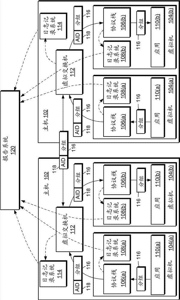
[0020] Figure 1 shows a virtual computing environment 100 with components and components most relevant to logging of events, inter-machine communication, and I / O protocol stack processing. The environment includes one or more virtual machine hosts 102 . For ease of description, two hosts 102 are shown in FIG. 1, which are shown with common reference numerals.

[0021] Each host 102 may implement one or more virtual machines 104(a) and 104(b). Similar components of the two illustrated virtual machines within each host are shown with the same reference numerals distinguished by suffixes (a) and (b). Components of the first virtual machine 104(a) are shown in each example with the appended suffix (a). Components of the second virtual machine 104(b) are shown in each example with the appended suffix (b). In the following discussion, when referring to either or both of the referenced components, the suffix may sometimes be omitted for ease of discussion.

[0022] Each virtual m...


PUM


Abstract

In a computing environment provided with a plurality of computers, log records are performed on events relevant to identifiers of corresponding activities. The computers may comprise virtual machines. When packets relevant to the activities are transmitted to a destination machine, the activity identifiers corresponding to the activities are transmitted together with the packets and are used by the destination machine in log record of the events. Thus, the events of two machines can be interrelated to the activities where they belong.

Description

Background technique [0001] Network communications and other computer input / output (I / O) operations are often implemented using a variety of protocols. Low-level protocols typically interact with device hardware or transmission media, while higher-level protocols typically interact with software applications. A series of protocol processing components from lower level protocols to higher level protocols is called a protocol stack, and each component within the stack is called a protocol layer. Data objects such as I / O packets typically pass serially through the layers of the protocol stack as they travel between applications and the physical transport mechanism. [0002] As an example, a network communication protocol stack may include the following protocols and corresponding layers: [0003] protocol layer [0004] HTTP application [0005] TCP transport [0006] IP Internet [0007] ethernet link [0008] IEEE 802.3u Physics. [0009] For debugging and troubleshoot...

Claims


Application Information

Patent Timeline
Patent Type & Authority Applications(China)
IPC IPC(8): H04L12/24G06F9/455
CPCG06F9/45533G06F15/16G06F9/455H04L41/069H04L12/6418
Inventor S.P.米里P.加格B.舒尔茨S.K.辛哈尔M.西瓦库马
Owner MICROSOFT TECH LICENSING LLC
Why Eureka
Try Eureka