
Piezoelectric ceramic bone conduction vibrator

A technology of bone conduction vibrator and piezoelectric ceramics, applied in piezoelectric/electrostrictive transducers, sensors, electrical components, etc., can solve problems such as uncomfortable wearing, heavy weight, and complex structure

Inactive Publication Date: 2013-01-16
西安康鸿环保科技有限公司
View PDF3 Cites 4 Cited by
  • Summary
  • Abstract
  • Description
  • Claims
  • Application Information

AI Technical Summary

Problems solved by technology

Its structure is complex, heavy and uncomfortable to wear

Method used


Image

  • Piezoelectric ceramic bone conduction vibrator
  • Piezoelectric ceramic bone conduction vibrator

Examples


Embodiment Construction

[0010] A bone conduction vibrator is an electroacoustic transducer that converts audio electrical signals directly into audio vibration signals without emitting sound. Only when it is in contact with the skull, the sound will be transmitted to the human cochlea and auditory nerve, so that people can hear the sound.

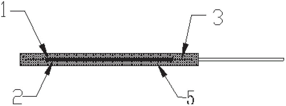
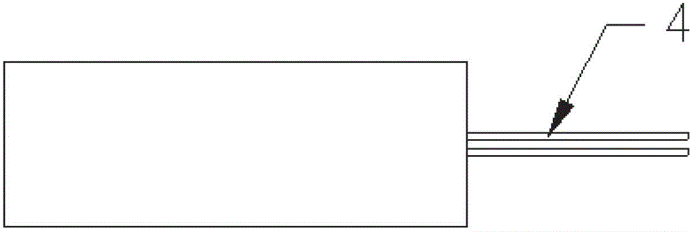
[0011] Such as figure 1 and figure 2 As shown, the present invention consists of two groups of piezoelectric ceramic sheets 1 and 2 with opposite polarities, which are attached to an elastic metal sheet 3 to form a bone conduction vibrator, and lead out the positive and negative electrodes of the piezoelectric ceramic sheet with a wire 4, and then use NS- 083 organic silica gel 5 encapsulates the bone conduction vibrator. Because the bone conduction speaker needs to touch the human skin and apply a certain pressure when it is used, so that its vibration can be transmitted to the skull and then to the auditory nerve. NS-083 organic silica gel 5 is soft and elas...


PUM


Abstract

The invention provides a piezoelectric ceramic bone conduction vibrator. Two groups of piezoelectric ceramic pieces with opposite polarity are attached on one elastic metal piece to form the vibrator, anodes and cathodes of the piezoelectric ceramic pieces are led out through wires, and organic silicon gel is used for packaging the vibrator. The piezoelectric ceramic bone conduction vibrator enables those with heating disorder to hear sound through the skull, achieves clear conversation in communication under high-noise environment, achieves the aim of greatly removing noise and simultaneously achieves the waterproof function of an underwater communication device.

Description

technical field [0001] The invention belongs to the technical field of electroacoustic transducers, and relates to an audio frequency vibration conduction technology. Background technique [0002] The frequency range of human audible sound is: 20Hz ~ 20kHz, the vibration in this frequency range will be transmitted to the human ear through the air, so that people can hear the sound. Conventional speakers produce sound through the audio vibration of the vibrating diaphragm. Bone conduction speakers, on the other hand, need to transmit audio vibrations directly to the skull instead of directly emitting sound. [0003] The conventional bone conduction speaker is an electromagnetic energy conversion method, and its vibration transmission is generally conducted through a hard material. And use padded sound-absorbing sponge and other materials to reduce sound leakage. Its structure is complex, heavy and uncomfortable to wear. At the same time, there is electromagnetic radiation...

Claims


Application Information

Patent Timeline
IPC IPC(8): H04R17/00
Inventor 陈耀刚
Owner 西安康鸿环保科技有限公司
Learn More